Here is some information for LT1, LS1, Vortec 4.8, 5.3, 6.0 wiring harnesses. There should be enough here to get you going in the right direction. Some of these I have pictures of completed harnesses I have modified for easy installation. I have a lot of pictures so please be patient and let them load. If you find this information useful, or have suggestion on something to add, let me know, I will try to get it done. For the most part, I have stopped accepting wiring harness work, for a few reasons, one being to improve the information on this website. My goal is to help the hobbyist to be able to complete a harness transformation by them self. I would only hope you send the PCM to me when it comes time for it. I do not charge for ANY information. If you use my info, send me a picture of your project, If I get enough response, I'd like to add a page on with a picture and some info about it. Thanks! -Brendan.
|
|||||
|
|
|||||

1992 to 1997 LT1 5.7 and L99 4.3 Wiring Harness Info Includes: Camaro/Firebird, Corvette, Caprice/Impala, Roadmaster
1996 to 1999 Vortec 4.3/5.0/5.7/7.4L Harness Schematics and INFO.
1999 to 2007 Vortec 4.8/5.3/6.0 Harness Wiring Info TONS OF INFO HERE, Please Read all the pages linked.
2007 to 2009 Vortec 4.8/5.3/6.0/6.2 Harness Information - New Harness Modification INFO added 11/6/2012! ECM Info HERE!
2010 to 2011 Camaro L99 - LS3 Information, Wiring, and so on
2001 Vortec 8.1L Info
1998 to 2002 Camaro/Firebird harness Wiring Info
For parts list for fuse block, obd2 diagnostic port, and wiring instructions, click here!
For those not wanting to tackle the wiring them selves, I will do it. Harness can have emission retained, or removed. All prices include reprogramming PCM and includes return shipping! All harnesses get diagnostic port, check engine light, fuse block and relays.
I WILL ONLY BE MODIFYING JUST A FEW HARNESSES A MONTH, EMAIL ME IF INTERESTED, AND I WILL DO MY BEST TO LET YOU KNOW AVAILABILITY AND A TIME FRAME. THANKS.
Please read the following for important information about you're wiring harness you send me for modification.
|
Wiring for gauges, dummy lights, and other non-essentials will be removed from the harness: Includes wires for water temp, oil pressure, oil level, oil temp. Use you're vehicles original oil pressure, water temp senders and wiring whenever possible, or aftermarket gauges. These can be left in harness if requested. | |
|
Cooling fan Relays are not part of my harnesses. I do provide the wires from the computer to turn on fan relays. You will need to wire up the relays to control the fans. | |
|
A/C controls will be removed. If you have aftermarket A/C unit, or using original A/C wiring from you're vehicle, you do not need the computer controlled A/C. If you wish to use computer controlled A/C, all sensors, switches, etc from the vehicle the engine came out of will have to be used. Add $25 if you want to keep computer controlled A/C. Also, you do not need an A/C idle up, the engine will detect the load on the engine and adjust idle controller to maintain idle speed. | |
|
I can remove transmission function and wiring for those who want to use a TH350,TH400, or TH700R4, or in some cases 4 speeds. This reduces the amount of wires and makes for a smaller harness bundle. | |
|
VSS - You should KEEP a vehicle speed sensor regardless of what transmission type you use. The PCM needs to know if vehicle is moving. Without the speed sensor, you can suffer from reduced fuel economy, reduced power, and idle problems. There are a few options for speed sensors on the transmissions with cable drive output. View this link at Dakota Digital website. I have used Dakota Digital SEN-4160 with good success. This is a 8000 pulse per mile sensor, that will allow cable speedometer hookup. I can program any PCM to accept any # of speed pulses. |
|
4x4 vehicles with manual transfer cases and ELECTRONIC TRANSMISSIONS must have speed sensor located between the transmission and the transfer case. There are aftermarket companies that offer an adaptor that fits the sensor in this location. Anytime you use an electronic transmissions, must keep 40 pulse per driveshaft revolution. If you have a TH350, TH400, or manual transmission, then it really doesn't matter where the speed sensor is located or the # of pulses, just so PCM knows vehicle is moving, as stated above. Check Novak Conversions for information on adapting transfer cases to 4L60E and other transmissions. These adaptors include a speed sensor. Keep in mind I need to know # of pulses and tire size/gear ratio when programming. |
Email me with any questions, and always check with me before sending a harness. Depending on how busy I am I can get harnesses done from within a week to as long as a month, just E-Mail and ask. I ask that you contact me via email with any information pertaining to what you want done to you're harness/programming. This is so I have a record of the conversation. I will almost always provide you a phone number to reach me after we have first talked via E-Mail. Thank you...
These prices are a base lines for harnesses in good condition with minimal repair needed.
LT1 & LS1 Camaro / Firebird from $300
LT1 Caprice / Impala / Roadmaster from $350 - stock fuse block is REMOVED and replaced with much smaller unit.
Vortec Truck/SUV 1999-2007 4.8/5.3/6.0 *including harnesses for Drive By Wire* from $350
Most Harnesses have following loose wires: * = Required for operation
12v+ Battery Connection*
Key 12v+ Connection* - this turns on a relay that powers up the fuse block, no high current draw
Fuel Pump Feed - 12v+ feed for fuel pump. Protected by fuse and controlled by the PCM
Brake Switch Signal - For automatics with lock up converter, the PCM needs signal when brake pedal is pressed. However, the signal needed is opposite how you're brake lights work. The PCM wants 12v+ constant on this wire when brake IS NOT pressed, and OPEN Circuit when the brake IS pressed. If you vehicle was equipped with a lockup trans to begin with, you probably already have the proper normally closed switch mounted by your brake light switch. If you do not, you can use a relay to perform the same thing. On most relays, there are 5 terminals, 2 of them turn the relay ON when provided ground/power. There are then a normally open leg and a normally closed leg on the relay and a supply. By feeding 12v+ on the supply leg, and hooking the Brake Switch Signal wire to the normally closed leg, you will now have the correct signal for the PCM. When the brake is pressed, 12v+ flows to brake lights, tap into this wire, and run it to the relay to turn the relay on. This will cause the normally closed leg to become open, thus turning OFF the 12v+ signal to the PCM. When you release the brake pedal, the relay will turn OFF, and then feed 12v+ to the PCM.
VSS Signal - This wire is a 4000 pulse per mile signal from the PCM used by some aftermarket speedometers. This can also be use for the electric cruise control boxes used on early 90s GM cars & trucks. PCM is reprogrammed to match tire size and axle ratio for you're swap, so this signal is calibrated.
TACH Signal - simply put, on LT1 with distributors, this comes from the negative side of the coil. On LS1, Vortec 4.8/5.3/6.0 this comes from the PCM, which generates this signal for a aftermarket tachometer.
Fan Controls 1,2 - Wires used to turn on relays for cooling fans. The PCM will supply a ground to turn on the relay. If you have an aftermarket fan setup which includes a temp sensor and relay to turn on the fan, you don't need to hook these up. If you want the PCM controlling the fans, use these. You will have to wire up the fans through relays. This is not included in my harnesses due to the high current draw of electric fans.
How to wire up a fan relay....or any device, just replace the FAN with whatever device you want to power.
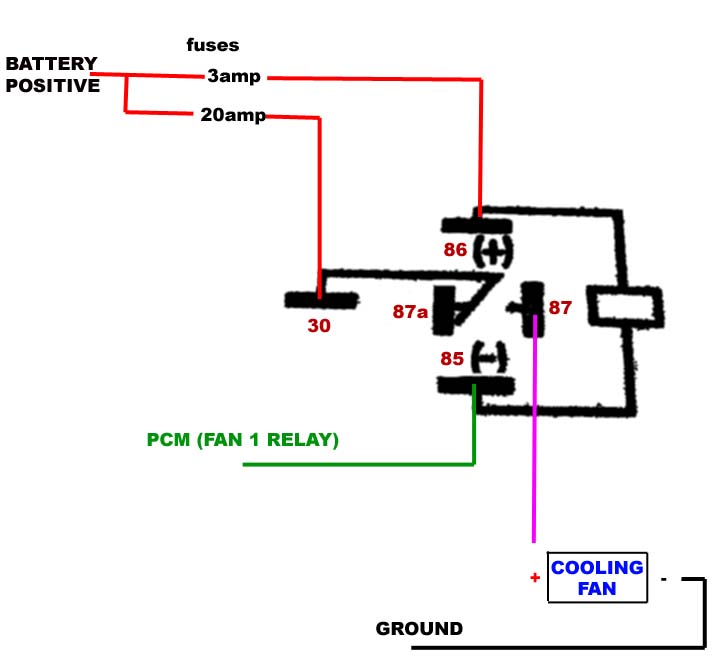
Wire going to terminal 30 & 87 should be 10-12 gauge to handle the current draw of the cooling fan. Terminals 85 & 86 can use 16-22 gauge just fine. Relay coil draws less then 1 amp.
Make sure the ground for the cooling fan is a good one, also ensure there is a good ground from the battery ( - ) side to the frame.
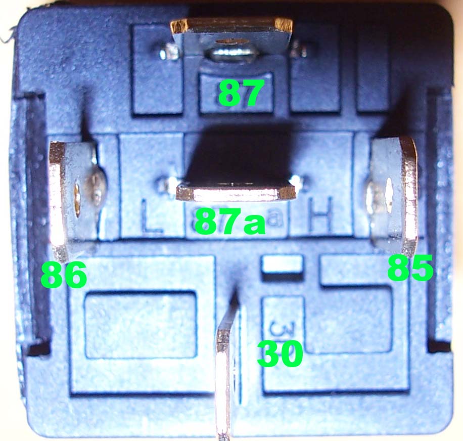
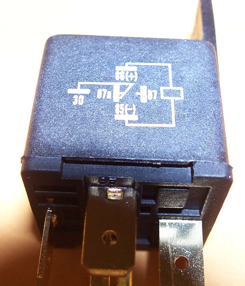
Here are some pictures of a typical automotive relay that can be found at most parts stores.
Contact Info
Brendan Patten
7227 Private Road 1830
West Plains MO 65775