PE4/AN4 on pin 60 is grounded, would have to lift the pin on the MCU to get it into some circuitry. Can be done, though. Turns out that this is an analog input, though-I started looking for the wrong thing I think.


PE4/AN4 on pin 60 is grounded, would have to lift the pin on the MCU to get it into some circuitry. Can be done, though. Turns out that this is an analog input, though-I started looking for the wrong thing I think.
Originally Posted by Xnke
 i have channel 0 listed as "knock filter(output?)" something goes on with that channel in the code, but I don't know what. maybe i'll take another look.
getting this PCM to log a wideband is just the same as another MAP sensor... just need a free a/d channel on the E-side(there MIGHT be enough space on the T-side to pull off an A/D read/store and jump back to normal code, but it would be close) and a little bit of space, maybe 20 bytes or so. as long as the channel doesn't have a pull-up resistor the way that the temperature channels do, then they should have just a low-pass filter between the PCM connector pin and either the micro's pin or the mux chip's pin. could also do something out of the ordinary and setup the calibration to only use one O2 sensor(like a FWD application does) and run a wideband signal through a voltage divider and feed it into the "spare" O2 sensor a/d channel. someone on this forum did that with my recommendation and they had good results, I just can't remember any details of the project.
lifting pins wouldn't be too bad, be better if one of the other circuits were already connected to the PCM connector.
seeing how it may help, here's what I have for the a/d channels:
e-side: channel 6 appears to be a mux channel
0: knock filter(output?)
1: right/rear O2
2: left/front O2
3: TPS
4:
5: MAT
6: MUX
7: MAP
6.00: A/C pressure sensor
6.20: fuel pump volts
6.40:
6.60: ???? (transferred to T-side as T-buffer 7, LSB, only used for DTC86 testing, value above d25 sets code)
6.80: A/C evaporator temp sensor
6.A0: ???? (transferred to T-side as T-buffer 12, LSB, only used for DTC43 testing), knock sensor input?
6.C0: coolant temp
6.E0:
*6.60 may be connected to quad driver fault line?
t-side:
0: ???? (read but not used except for factory test?)
1: TPS
2:
3: MAP
4: Trans Fluid
5:
6: Battery Volts
7: PCS Sense
1995 Chevrolet Monte Carlo LS 3100 + 4T60E
Still can't figure this one out. Pin 60, A/D channel 4, goes into one of the inner layers of the board-it appears to be a four-layer board. It probably isn't actually grounded. I have located a pad on the lower side of the board that shows continuity, but it also shows continuity to pin 59, A/D channel 0. Channel 0, the one you have as a possible knock filter output, is an input-only pin, according to the MC68HC11F1 documentation. Must be the output of the knock filter going in to the MCU.
more stuff I need to investigate further, I'm guessing at channel 0 based only on what the code does with it. with 6.A0 also appearing as knock sensor related, I really don't know what to think.
1995 Chevrolet Monte Carlo LS 3100 + 4T60E
Picked up some PCM wiring harness connectors today at the parts yard, plus the forward lamp harness connector for a Camaro so I can not hack up the F-body harness as much. Also grabbed a MAP sensor from a supercharged Buick, as well as four more M90 blowers...I have enough blowers now for a while. All of them just need the coupler replaced in the snout, fresh oil, and they're good as new.
Also, my Northstar throttle showed up, complete with busted IAC...hoping the SFI IAC will fit down in its place. I don't want to buy another one if I don't have to.
Waiting on an intercooler core, 120mmx120mmx42mm, two-pass unit.
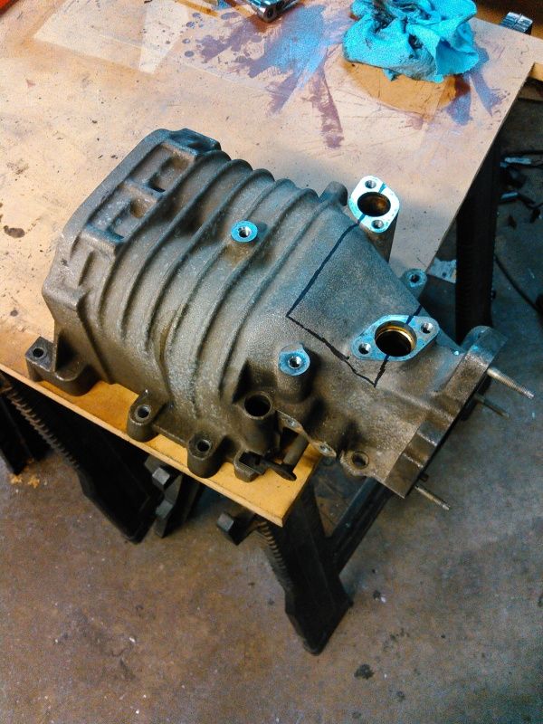
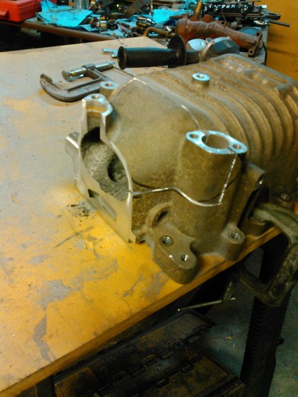
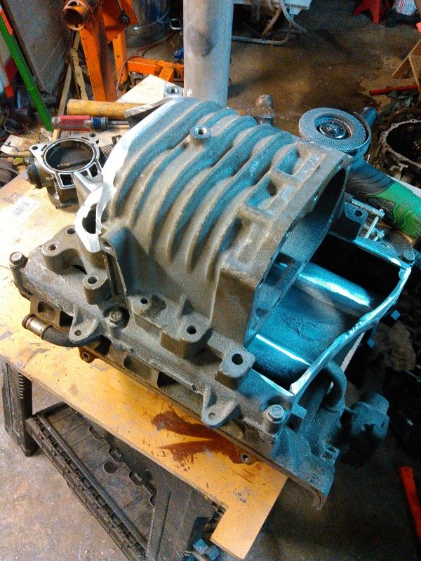
Tonight was spent reworking the supercharger case. Trimmed off the original throttle body flange, started opening up one side of the case.
Here's the case trimmed, marked out and starting to open it up:
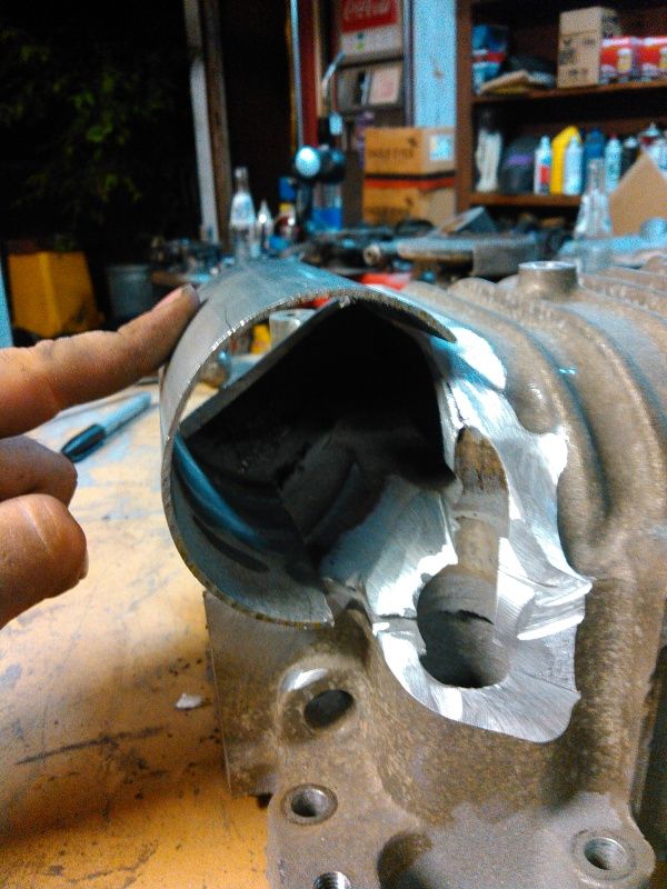
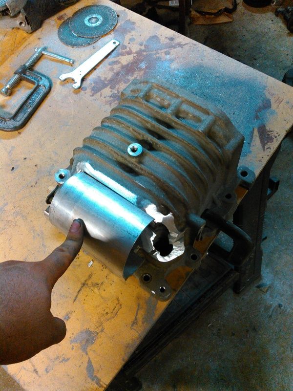
Started mocking it up with a section of 3" tubing, getting a feel for how things are going to work out. Will need a bit of welding to get things radiused correctly.
Another look:
Positioned on top of the upper manifold, trying to get an idea of how the throttle body will set. It's a 75mm unit from a Northstar V8.
A couple more hours has this fitted and fixed.
Did some more hunting around tonight in the ECM-There is no pin currently connected to the exterior of the ECM that is tied to Pin 60/AN4 of the E-side 'HC11. A LOT of pins have 5.6K or 9K resistance to that pin, though, which reaffirms my suspicion that it's grounded-as all unused analog input pins should be for good practice.
I don't have any method of currently flashing the PCM right now, haven't bought Winflash because to be honest, I don't really trust the TunerCATS website, and I don't have 50$ to drop on the Madtuner software right now. As soon as I do, I'll lift the AN4 pin on the auto ECM and see if I can twiddle the line, is there any indicator in Tunerpro that would tell me if I have the right pin?
not currently read/stored anywhere in the code, but it isn't like it would take much to patch it in.
1995 Chevrolet Monte Carlo LS 3100 + 4T60E
nearly have this 93 PCM mapped out to my satisfaction... I've got a text document with my findings in it and more than a few photographs along the way, suffice to say that the e-side still has a few tricks left in its sleeve.
1995 Chevrolet Monte Carlo LS 3100 + 4T60E
BARO update on boosted engine is a challenge with one sensor. Dedicated BARO on one channel is a waste of data. Update could be accomplished during conditions which enable DFCO. Single sensor solution could involve electric vacuum switching valve on MAP line. When DFCO becomes active, engage valve and open MAP to atmo to take quick BARO reading. Interrupt BARO reading routine if TPS increases. Similar could be done using Baro sensor that shares MAP signal line. Electrically switch sensors during DFCO while monitoring TPS for change in case it's not appropriate to disconnect MAP.
hmm..... i'll have to see what kind of outputs are still available to accomplish a little mini-muxing of the MAP circuit. as-is, there are a few open A/D channels on the E-side, i'll need to do a final pass on everything tonight.... figuring this stuff out at 4AM, I skipped a few things along the way.
1995 Chevrolet Monte Carlo LS 3100 + 4T60E
It's really cool that you're putting the time into this. I hope the V660 crowd picks it up and runs with it. FWIW none of the GM turbo code bases did BARO updates properly. IIRC $58 will arbitrarily assign a BARO value at key on if a number of conditions aren't met.figuring this stuff out at 4AM, I skipped a few things along the way
I would have thought GM would have done something like that for the Pikes Peak TGP considering the huge change in elevation, but I'm told it ran a rather stock-ish calibration.
1995 Chevrolet Monte Carlo LS 3100 + 4T60E
^ I recognize that situation.... I think the wrong button got pressed.
anyways, i'll post this stuff as I reconfirm it, turns out I got sloppy last night while probing around with the meter. I need to pull pics off of the camera and label the chips as I have them written down, but I do have some solid info on some important stuff.
E-side:
U:
1 16126532
2 56597
3 16127475 C94R 68HC11F1
4 37414
5 27474
6 M32AB 89551
7 16155187 AN28F256A flash PROM
8 P31AB 30965
9 P31AB 30965
10 M32AB 89551
11 P31AD 57245 logic gate(AND)
12 P31AB 47816
13 129170 CP03597
IRF9395 INJECTOR DRIVERS
8.388MHZ CRYSTAL
MISSING: U14 AND 2 LARGE TRANSISTORS
missing transistor closest to knock filter controls pin C5, other controls C6, these are PCS high and PCS low.
6811 A/D:
0 - battery volts
1 - right/rear O2
2 - left/front O2
3 - TPS
4 - pin A28(1K pulldown, 10K isolation)
5 - IAT
6 - a/d mux chip's output
7 - MAP
OC1 and OC4 are broken out, but function unknown
E-side mux chip is located on T-board
mux'd A/D:
0 - a/c pressure
1 - fuel pump monitor
2 - 10K isolator, 909 ohm pullup? (pin A7)
3 - 10K+? RC filter + 511K pulldown (pin A4)
4 - a/c temp sensor
5 - 200K to 2nd pin on knock filter(connected to sensor through 100 ohm resistor)
6 - coolant temp
7 - 20K to pin 1 of E-side PROM program circuit
T-side:
U:
15 64606 ALDL comms chip
16 034987 O2 amplifier
17 034987 O2 amplifier
18 16132083
19 16084368
20 16084523
21 P29AB 45153 8 channel mux for E-side A/D
22 P39AB 61285
23 P31AD 57245 logic gate(AND)
24 56597
25 16155187 AN28F256A flash PROM
26 16127475 C94R 68HC11F1
27 45980 63634 quad driver
28 45980 63634 quad driver
29 16180566 fuel pump relay driver
30 34992 power supply
31 M32AD 41398 connected to e-side via ribbon, inside row, pin 11
32 45980 63634 quad driver
33 34993 IAC driver
34 45980 63634 quad driver
MISSING U35 AND U36
A/D:
0 - coolant temp
1 - TPS
2 - 3rd pin of knock filter
3 - MAP
4 - trans temp
5 - pin A28(1K pulldown, 10K isolation)
6 - battery volts
7 - PCS sense
Last edited by RobertISaar; 08-10-2015 at 07:17 AM.
1995 Chevrolet Monte Carlo LS 3100 + 4T60E
Ahh... Yep.^ I recognize that situation.... I think the wrong button got pressed.
I've seen a few GM "race" cals and they weren't all that exciting. Codes shut off, CL disabled, emissions disabled, and sometimes more timing to go with race fuel. I've actually got a rocketparts Q4 cal here along with one from the Snakeskinner LT5. On both cals you can compare scan ID and data bytes to determine the stock cal they were made from.
 Posting Permissions

 Reply With Quote


Bookmarks