Results 1 to 15 of 509

Thread: 1997 F-Body ECM

Hybrid View

Previous Post Previous Post   Next Post Next Post
  1. #1
    Fuel Injected!
    Join Date
    Mar 2013
    Posts
    1,478
    I still insist the response on successful upload must be 73, not 78.
    The loading address at 1900 might not be suitable for initial upload, try 0000 and see what happens.
    Try running both sides as per the quote and upload GM code to see does it work as expected. Single side upload can lead to undesired effects.
    request mode 36 $10 accsess
    <6C 10 F0 34 80 03 56 00 00 80
    >6C F0 10 74 00 44 00

    request mode 36 $18 accsess
    <6C 18 F0 34 80 03 F3 00 00 00
    >6C F0 18 74 00 44 00

    download and execute Main LOOP $18
    <8C FE F0 3F
    <6D 18 F0 36 80 03 F3 00 00 00 20 31 20 2F 00 00 00 00 ..
    >6C F0 18 76 00 73 00

    download and execute Main LOOP $10
    <8C FE F0 3F
    <6D 10 F0 36 80 03 56 00 00 80 20 3D 20 00 FF FF 7E 02 ..
    >6C F0 10 76 00 73 00
    Pcm can`t execute highspeed on it`s own. It must be requested by the tool. When the pcm recieves A1 request it sets a register to command the dlc to enter highspeed. Actually the pcm doesn`t care since the highspeed is handled by DLC. Dlc is also set to revert to x1 mode on the first x1 message it receives when is in x4 mode.

    Figuring this stuff by looking at the code is next to impossible or it will take alot more time than you can think of. Some experiments reveal stuff much faster.

  2. #2
    Fuel Injected!
    Join Date
    Jan 2019
    Location
    Canada
    Posts
    477

    Download code snips

    Hi,
    I want to reply to all your thoughts, this post is just on the first bit

    Quote Originally Posted by kur4o View Post
    I still insist the response on successful upload must be 73, not 78.
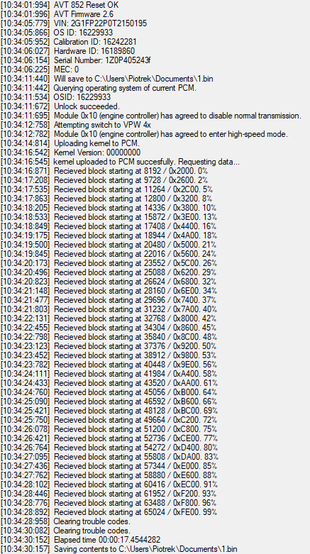
    I think response 73 is reserved for download without execute. In my dictionary of code responses: Code $73 - Block Transfer Complete/Next Block. This seems to match with what I see. Here is a screen shot of my app when I download without execute...

    DLCAP3.jpg

    I have tried loading to $0000, $1810 and $1900. Code seems to get hit no matter where I place it.

    Also... regarding response code sent, here are some commented code snips. First is where I believe the testing is done to verify the parameters place downloaded code in ram and not elsewhere

    Code:
    DD0B  B6 1B FF    	LDAA   $1BFF           ; GET LENGTH BITS 16:23
    DD0E  85 7F       	BITA   #$7F            ; TEST FOR EXECUTE DOWNLOAD FLAG
    DD10  27 05       	BEQ    $DD17           ; 
    
    DD12  CC 74 41    	LDD    #$7441          ; IMPROPER DOWNLOAD TYPE
    DD15  20 21       	BRA    $DD38           ; 
    
    
    DD17  B6 1C 11    	LDAA   $1C11           ; TEST ADDRESS OUT OF RANGE FLAG
    DD1A  85 40       	BITA   #$40            ; 
    DD1C  27 05       	BEQ    $DD23           ; 
    
    DD1E  CC 74 42    	LDD    #$7442          ; CAN'T DOWNLOAD TO SPECIFIED ADDRESS
    DD21  20 15       	BRA    $DD38           ; 
    
    DD23  85 20       	BITA   #$20            ; TEST LENGTH ERROR FLAG
    DD25  27 05       	BEQ    $DD2C           ; 
    
    DD27  CC 74 43    	LDD    #$7443          ; CAN'T DOWNLOAD NUMBER OF BYTES REQUESTED
    DD2A  20 0C       	BRA    $DD38           ; 
    
    DD2C  B6 1B FE    	LDAA   $1BFE           ; READ REQUESTED MODE
    DD2F  81 34       	CMPA   #$34            ; REQUEST DOWNLOAD- TO PCM
    DD31  26 13       	BNE    $DD46           ; 
    
    DD33  CC 74 44    	LDD    #$7444          ; READY FOR DOWNLOAD
    DD36  20 0C       	BRA    $DD44           ;
    This gives detail of how codes 42, 43 and 44 are arrived at.

    Next snip is where dl frame is received and evaluated
    Code:
    DD77  7D 1B FF    	TST    $1BFF           ; TEST FOR EXECUTE FLAG $80
    DD7A  2A 23       	BPL    $DD9F           ; BRANCH TO CONTINUE DOWNLOAD
    
    DD7C  CC 76 78    	LDD    #$7678          ; BLOCK TRANSFER MESSAGE CORRECTLY RECEIVED
    DD7F  B7 1C 0B    	STAA   $1C0B           ; DATA BYTE 0
    DD82  F7 1C 0D    	STAB   $1C0D           ; DATA BYTE 2
    DD85  B6 1B FF    	LDAA   $1BFF           ; 
    DD88  B7 1C 0C    	STAA   $1C0C           ; DATA BYTE 1
    
    DD8B  B6 1B FC    	LDAA   $1BFC           ; 
    DD8E  B7 1C 0A    	STAA   $1C0A           ; 3RD HEADER BYTE
    
    DD91  C6 06       	LDAB   #$06            ; MESSAGE BYTE COUNT
    DD93  BD DE 37    	JSR    $DE37           ; SEND MESSAGE TO THE DATA LINK
    
    DD96  21 28       	BRN    $DDC0           ; BRANCH NEVER??
    
    
    * EXECUTE CODE AT ADDRESS IN BYTE 5 AND 6
    DD98  FE 1C 03    	LDX    $1C03           ; 
    DD9B  AD 00       	JSR    $00,X           ; EXECUTE DOWNLOAD FROM ADDRESS
    
    DD9D  20 21       	BRA    $DDC0           ; 
    
    DD9F  CC 76 73    	LDD    #$7673          ; BLOCK TRANSFER COMPLETE/NEXT BLOCK
    This gives detail to how codes 78 and 73 are arrived at.

    In some places frames are not responded to. Also I note that the execution is JSR $00,X. This means that the stack shouldn't be re-assigned if the routine plans to return. While my download routine does not return, my re-init of the stack could be creating troubles for interrupt code.

  3. #3
    Fuel Injected!
    Join Date
    Jan 2019
    Location
    Canada
    Posts
    477

    Download code snips II

    Quote Originally Posted by kur4o View Post
    Try running both sides as per the quote and upload GM code to see does it work as expected. Single side upload can lead to undesired effects.
    Interesting... download to both sides may set/clear some flags. Hmmmmm

    Quote Originally Posted by kur4o View Post
    Pcm can`t execute highspeed on it`s own. It must be requested by the tool. When the pcm recieves A1 request it sets a register to command the dlc to enter highspeed. Actually the pcm doesn`t care since the highspeed is handled by DLC. Dlc is also set to revert to x1 mode on the first x1 message it receives when is in x4 mode.

    Figuring this stuff by looking at the code is next to impossible or it will take alot more time than you can think of. Some experiments reveal stuff much faster.
    It does seem to me that when DL commands are issued, the code places the DLC in 4X mode. In the code

    Code:
    ************************************************
    * DATA LINK CONTROL GET FRAME
    ************************************************
    * 1X MODE
    DC50  8E 1C 2A    	LDS    #$1C2A          ; SET STACK
    DC53  0F          	SEI                    ; DISABLE INTERRUPTS
    DC54  20 09       	BRA    $DC5F           ; GET FRAME
    
    * 4X MODE
    DC56  8E 1C 2A    	LDS    #$1C2A          ; SET STACK
    DC59  CC 18 13    	LDD    #$1813          ; CONFIGURE DATA LINK CONTROLLER
    DC5C  FD 10 60    	STD    $1060           ; FOR 4X MODE
    
    * INITIALIZE CHECKSUM
    DC5F  4F          	CLRA                   ; ZERO FRAME BYTE COUNT 
    DC60  5F          	CLRB                   ; AND CHECKSUM
    DC61  FD 1C 05    	STD    $1C05           ; 16 BIT SUM
    
    DC64  B6 1C 11    	LDAA   $1C11           ;
    The Eside seems to target $DC50 while the Tside goes to $DC56. There is a mindblowing structure of recovery if the 4X generates an error. There may be a way to have the Tside fall back to 1X. I will try some experiments on this. I have had a download on the Tside by sending the download frame a number of times. It just seems like the code was written with the exact tester they planned for in mind. All this goes away if I get another module and generate test data using another 68HC58 DLC.

    I have some time today and will give this another try.

  4. #4
    Fuel Injected!
    Join Date
    Jan 2012
    Location
    Poland
    Posts
    147
    Quote Originally Posted by Tom H View Post
    There is a mindblowing structure of recovery if the 4X generates an error. There may be a way to have the Tside fall back to 1X. I will try some experiments on this. I have had a download on the Tside by sending the download frame a number of times. It just seems like the code was written with the exact tester they planned for in mind. All this goes away if I get another module and generate test data using another 68HC58 DLC.
    For 1X fallback, you need to check for "break received" on the DLC, I've extracted it from 98 "black box" PCM code. Anyway, SPS code always goes back to 4X, but if you skip the 4X switch it will work correctly in 1X.

    Anyway, I wanted to show off a little, here's a shot of working T-side read using PCM Hammer derived software :) The main kernel barely fits in the 1kB RAM, but I managed to squeeze it in there :)


    I still have some issues communicating with E-side, but it all goes in a good direction :)

  5. #5
    Fuel Injected!
    Join Date
    Jan 2019
    Location
    Canada
    Posts
    477
    looks like great progress. For me, I have set the download aside for a bit. I have run into problems with understanding the queue of messages. In code from the '97 processor there is a scheme for some sort of FIFO. This lets reply from requests complete before working through the next request. I believe it is in that code where problems exist for me. It looks like one location is in normal circumstances set to $0. When a reply to a request is lengthy, one reply is sent out each time the subroutine is called. This takes place until the request has been serviced.
    This is also the code that looks after Mode $34 commands. It seems like mode $34 requests to the Tside do not set this location and thus will not process $36 command. When I figure it out, I will describe for the forum.

    In order to figure it out I have disassembled the Mode $19 command. It makes use of this extended service location. I have completed this now but need to go back and look at the service code that parses commands from the DLC.

    Great to see your progress!!
    Cheers,
    -Tom

    PS - Does anyone have information on Mode $19 ? I thought it would be part of SAE J2190 but is not listed there. Mode $18 is listed there and they seem very similar! What am I missing here?
    Last edited by Tom H; 05-01-2019 at 05:53 PM.

  6. #6
    Fuel Injected!
    Join Date
    Jan 2012
    Location
    Poland
    Posts
    147
    Mode $19 is "Read DTC Information", so it should return status of every specified DTC. I'm not sure exactly...

    I've made a huge progress last couple of days! E-side SPI comms are finally working and I have working T-side and E-side read software!


  7. #7
    Fuel Injected!
    Join Date
    Jan 2019
    Location
    Canada
    Posts
    477
    First off Congratz dzidaV8. Fantastic that you have the download/upload solved!!

    I was asking after Mode 19 because IF it is similar to Mode 18, a whole bunch of memory locations can be identified. There are a number of tables for DTCs that try to classify the use. J2190 calls them up for mode 18 as follows:

    bit 7 Warning lamp illuminated for this code
    bit 6 Warning lamp pending for this code, not illuminate but malfunction was detected
    bit 5 Warning lamp was previously illuminated for this code, malfunction notcurrently detected, code not yet erased
    bit 4 Stored trouble code
    bit 3 Manufacturer specific status
    bit 2 Manufacturer specific status
    bit 1 Current code - present at time of request
    bit 0 Maturing/intermittent code - insufficient data to consider as a malfunction

    If I can say for sure that the status is the same for Mode 18 and 19, the definition of 144 bits become determined. I can't find any definition of Mode $19 and think it may be a GM special/non-standard. I have disassembled and commented the code to the point where this all is taking shape. Just don't know the intent of the code completely.

    -Tom

  8. #8
    Fuel Injected!
    Join Date
    Jan 2019
    Location
    Canada
    Posts
    477
    I had a close look at Mode 3C used to read various parameters from the PCM including VIN...

    MODE $3C

    Mode $3C is loosely defined in SAE J2190. In my PCM (calibration #?16236217?) the request looks as follows:

    H0 H1 H2 MODE BLOCK# <CRC>

    Header 0: Priority: Any, Three byte consolidated header, IFR not allowd, Physical addressing, Node to Node
    Header 1: Target address or destination can be $10 (engine controller) or $FE (all nodes)
    Header 2: Source address should be one of the off board tester/diagnostic tool addresses.

    For testing I have used $4C $10 $F0 for header values. The Mode I am looking at is $3C.

    Supported block numbers are:
    $01 through $08, $0A, $0B, $40 through $49, $A0

    The data associated with each of the blocks is returned based on a look up table.

    TSIDE
    Block# Start Data Content
    Address Length

    $01 $0E24 $06 VIN BLOCK 1
    $02 $0E29 $06 VIN BLOCK 2
    $03 $0E2F $06 VIN BLOCK 3
    $04 $0E04 $04 VIN BLOCK 4
    $05 $0E08 $04 VIN BLOCK 5
    $06 $0E0C $04 VIN BLOCK 6
    $07 $0E10 $04 VIN BLOCK 7
    $08 $0E20 $04 VIN BLOCK 8
    $0A $2000 $04 Calibration Number (binary)
    $0B $0262 $04
    $A0 $0E35 $01

    ESIDE moved by SPI to Tside RAM
    Block# Start Data Content
    Address Length

    $40 $182A $02
    $41 $182C $06
    $42 $1832 $06
    $43 $1838 $05
    $44 $183D $06
    $45 $1843 $06
    $46 $1849 $05
    $47 $184E $06
    $48 $1854 $06
    $49 $185A $05

    One interesting note...
    Block $01 is special in that while the LUT calls for 6 bytes of VIN info to be sent there is a special branch for this block only. Block 1 sends the first data as $00 in all cases, followed by the five bytes starting at EEPROM $0E24. It is not clear to me why things were done in this way.

    I wonder if a complete map of EEPROM content is available somewhere?

    There are 512 bytes of EEPROM in each of the Tside and Eside processors. Has anyone looked into the use of all this?

    -Tom

Similar Threads

  1. 94-95 LT1 $EE Y-body vs. F/B-body PCM differences
    By johnny_b in forum GM EFI Systems
    Replies: 5
    Last Post: 01-15-2023, 02:41 PM
  2. Tuner Pro XDF 1999-2000 F Body + Y Body
    By john h in forum OBDII Tuning
    Replies: 33
    Last Post: 02-02-2020, 11:12 PM
  3. Replies: 31
    Last Post: 09-20-2018, 06:00 AM
  4. F-body engine install to B-body
    By serge_an in forum GM EFI Systems
    Replies: 4
    Last Post: 09-22-2016, 02:51 PM
  5. 95 F-body Fuel Pump with 95 B-Body Engine/Tank
    By EPS3 in forum GM EFI Systems
    Replies: 7
    Last Post: 09-19-2016, 02:40 PM

Bookmarks

Posting Permissions

  • You may not post new threads
  • You may not post replies
  • You may not post attachments
  • You may not edit your posts
  •