Page 1 of 3 123 LastLast
Results 1 to 15 of 41

Thread: Issues with TBI 7747 tune

  1. #1
    Fuel Injected! srobertsfsj's Avatar
    Join Date
    Apr 2012
    Location
    Denver, CO
    Posts
    81

    Issues with TBI 7747 tune

    Hi Everyone, I am having issues with my first EFI install so I was hoping I could get a little direction. I am new to this so please bare with me, I do pick up stuff fast but I will probably use a lot of incorrect terms. :)

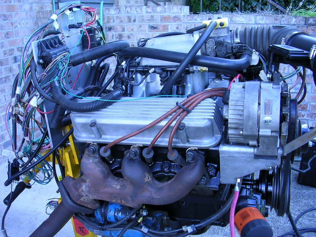
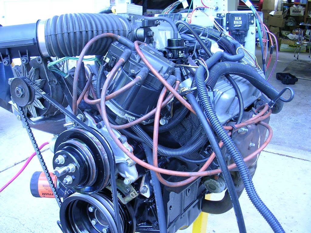
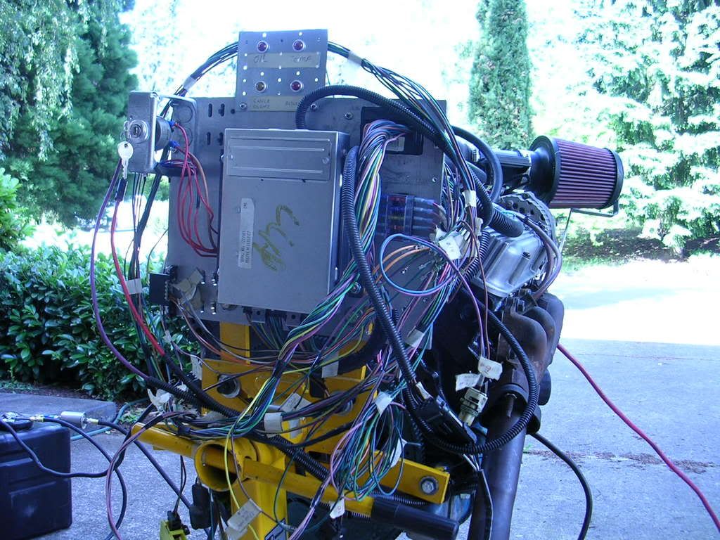
    First the specs. Spent the last week installing junkyard TBI install on a 1986 Jeep Grand Wagoneer with a 360cid and auto tranny, HEI with 7pin ign module, 7747 ECM and 5.0L injectors. I was fortunate to have another member of this site help me today. FSJ Guy came by the house to help me with the tune and provided a good starting bin file. I am using TunerPro RT 5.0 with a USB autoprom. The base timing with the bypass wire disconnected was set to 12 deg.

    Here are the issue we ran in to.

    1. Idle pulses between 600 and 1000 rpms, tried lean and rich settings but no change
    2. With bypass wire plugged in the timing is around 60deg at idle. timing shouldn't change at idle, correct?
    3. Any acceleration would cause the engine to backfire and die. Timing issue, correct?
    4. Engine would die shifting into drive.

    My first uneducated thoughts, possibly bad IAC, incorrect 7-pin HEI module wiring and/or wrong injectors for application. Im sure FSJ Guy will also comment with his observations. Thoughts?

    Thanks!

    Scott R.

  2. #2
    Super Moderator Six_Shooter's Avatar
    Join Date
    Feb 2011
    Posts
    2,968
    Is that 60 degrees checked with a timing light?

    Fix that before looking at ANYTHING else.

    With the bypass wire plugged in, you should be between 17 and 25 degrees (depending on what the engine actually wants), at idle. The ECM will command more timing at idle than what base timing is.

    I would suspect that the bin file was originally set for 0* base advance, and so your base timing should match that, or whet is set in the bin, otherwise, you will have more timing than actually commanded.
    The man who says something is impossible, is usually interrupted by the man doing it.

  3. #3
    Fuel Injected! srobertsfsj's Avatar
    Join Date
    Apr 2012
    Location
    Denver, CO
    Posts
    81
    Hi Six_Shooter. Yes the timing was checked with a timing light both before (12deg) and after(60+ deg) the bypass wire was plugged in. The bin file "Initial Spark Advance" parameter is set to 12 deg (actually 11.95).

  4. #4
    Super Moderator Six_Shooter's Avatar
    Join Date
    Feb 2011
    Posts
    2,968
    You need to get that advance under control before doing anything else.
    The man who says something is impossible, is usually interrupted by the man doing it.

  5. #5
    Fuel Injected! srobertsfsj's Avatar
    Join Date
    Apr 2012
    Location
    Denver, CO
    Posts
    81
    agreed, just not sure why it would be doing that.

    I wired the 7-pin module based on this diagram.

    http://www.slantsix.org/articles/dib...odule-schm.jpg

    One question I have and maybe it cant be answered here. This diagram does not account for wire B3 which, I believe, is a reference low wire. I wonder if that is the issue. Does anyone know where this wire goes in a 7-pin setup?

  6. #6
    Super Moderator Six_Shooter's Avatar
    Join Date
    Feb 2011
    Posts
    2,968
    B3 is a ground. It is used to keep the ground reference between the ICM and the ECM the same. It is a Black/Red (black with red stripe) wire.
    The man who says something is impossible, is usually interrupted by the man doing it.

  7. #7
    Super Moderator dave w's Avatar
    Join Date
    Feb 2011
    Posts
    6,291
    I see what might be happening? So the distributor being used is the "Large Cap" with the coil in the Cap?

    dave w

  8. #8
    Fuel Injected! srobertsfsj's Avatar
    Join Date
    Apr 2012
    Location
    Denver, CO
    Posts
    81
    Yes it is the coil in cap style

  9. #9
    We were playing around with the timing settings in the bin file. The maximum timing set was around 30 or so. Nowhere near the 60+ degrees we were seeing with the timing bypass connected. I can't figure out why the timing was so advanced.

    I'm familiar with the 8 pin ignition module, but it did appear that we had the 7 pin module hooked up correctly.
    Familiar with 1227747 and 16197427 PCMs

  10. #10
    Poking around the net shows that the 7 pin module is similar to the 8 pin module. The 8 pin module just has an extra ground wire.

    Scott, you might want to compare the wiring for the 7 pin module with the wiring diagram for the 8 pin module in the schematics that I emailed you.
    Familiar with 1227747 and 16197427 PCMs

  11. #11
    Super Moderator dave w's Avatar
    Join Date
    Feb 2011
    Posts
    6,291
    Quote Originally Posted by srobertsfsj View Post
    I wired the 7-pin module based on this diagram. http://www.slantsix.org/articles/dib...odule-schm.jpg
    The ECM in the above link is for a Buick V6 MPFI application. I don't have the schematics in front of me at the moment, but I'm thinking the PIN locations for the distributor ignition module are different from a Buick ECM and Chevy TBI ECM?

    dave w


  12. #12
    Administrator
    Join Date
    May 2011
    Location
    Lakes Region, NH
    Age
    54
    Posts
    3,859
    REF_LOW at the distributor should be connected to REF_LOW at the ecm in order to reduce noise. Do not connect to ground.


    Pickup coil P and N should be connected properly and pickup coil is rotation specific. Using wrong coil or connecting coil in reverse will result in excess offset as REF pulse and bypass mode spark pulse are generated on zero crossing of falling wave. Long story short, with pulses generated 90 deg apart, wrong coil/connection generates spark up to 45 deg off. You can swap the P and N leads and see if everything is fixed but mark it down somewhere so you're not chasing the same problem if you ever change the pickup coil later.

  13. #13
    RIP EagleMark's Avatar
    Join Date
    Feb 2011
    Location
    North Idaho
    Age
    64
    Posts
    10,477
    1project2many REF_LOW at the distributor should be connected to REF_LOW at the ecm in order to reduce noise. Do not connect to ground.
    Well that's what the large cap HEI for EFI shows.


    Six_Shooter B3 is a ground. It is used to keep the ground reference between the ICM and the ECM the same. It is a Black/Red (black with red stripe) wire.
    Well that's what the newer EFI shows.


    So how does that correspond to what this shows? Other then you have an extra black wire red stripe from newer ECM that goes to ground in ECM? So ground it, or ground it to 7 Pin module?

    Attached Images Attached Images

    1990 Chevy Suburban 5.7L Auto ECM 1227747 $42!
    1998 Chevy Silverado 5.7L Vortec 0411 Swap to RoadRunner!
    -= =-

  14. #14
    Super Moderator dave w's Avatar
    Join Date
    Feb 2011
    Posts
    6,291
    Quote Originally Posted by 1project2many View Post
    REF_LOW at the distributor should be connected to REF_LOW at the ecm in order to reduce noise. Do not connect to ground.
    I agree with this statement. Many of the EFI harness I've worked on, will have the black wire with red stripe grounding (REF_LOW) from an internal connection inside the distributor. In my thinking, this puts the ECM REF_LOW as the same REF_LOW as the distributor. The distributor "should" be getting ground from the block, but I've actually measured a small DC voltage from the distributor housing to the Battery Negative terminal!

    dave w

  15. #15
    RIP EagleMark's Avatar
    Join Date
    Feb 2011
    Location
    North Idaho
    Age
    64
    Posts
    10,477
    That's interesting! Wonder if the distributor gasket is causing this?

    1. The newer small cap 8 pin has a ground through module by way of mounting bolt to distributor and also a wire to B3 of ECM which shows as ground.
    2. The older large cap 7 pin has a ground through module by way of mounting bolt to distributor and also a black red wire to Ref Low which shows 1.01v in ECM but ground in module.

    I don't remember doing anything with B3 from newer small cap ECM with large cap HEI. But now I think I would run B3 to distributor for ground and leave other wires they way diagram shows above which is what I used before.

    Then see if you still have 60 degrees advance, look at changing wires from pickup coil to EST module like 1project2many suggested. But my experiance with that is it will only change advance from BTDC to ATDC. So you may have a bad module... if your distributor is set to 12 advance wire disconnected and you change pickup coil wires it will be 12 retard... but I don't think I ever did this with large cap HEI 7 pin module, I have done it with duraspark conversion and GM/Hybrid small cap machined to conversion motor distributor when conversion engine turned distributor reverse rotation. So 1project2many seems to know what is going on here with this large cap module.

    1990 Chevy Suburban 5.7L Auto ECM 1227747 $42!
    1998 Chevy Silverado 5.7L Vortec 0411 Swap to RoadRunner!
    -= =-

Bookmarks

Posting Permissions

  • You may not post new threads
  • You may not post replies
  • You may not post attachments
  • You may not edit your posts
  •