Page 7 of 24 FirstFirst ... 2345678910111217 ... LastLast
Results 91 to 105 of 349

Thread: Anyone worked with the 16196397 yet?

  1. #91
    Fuel Injected!
    Join Date
    Jun 2015
    Age
    36
    Posts
    354
    While I wait on my *hopefully* FTDI branded cable, I did some more work on the intake manifold.

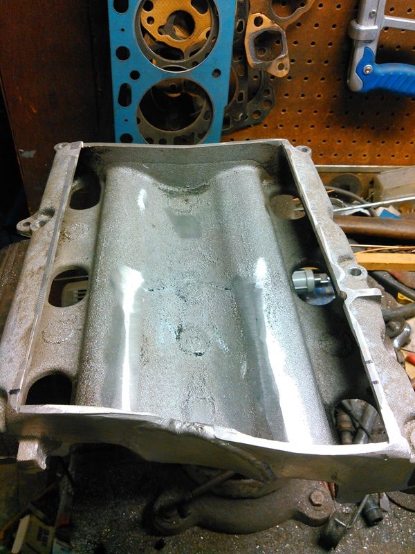
    First thing to do is get it cleaned up a bit and start measuring how far off I was with the angle grinder.


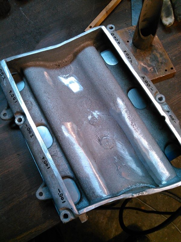
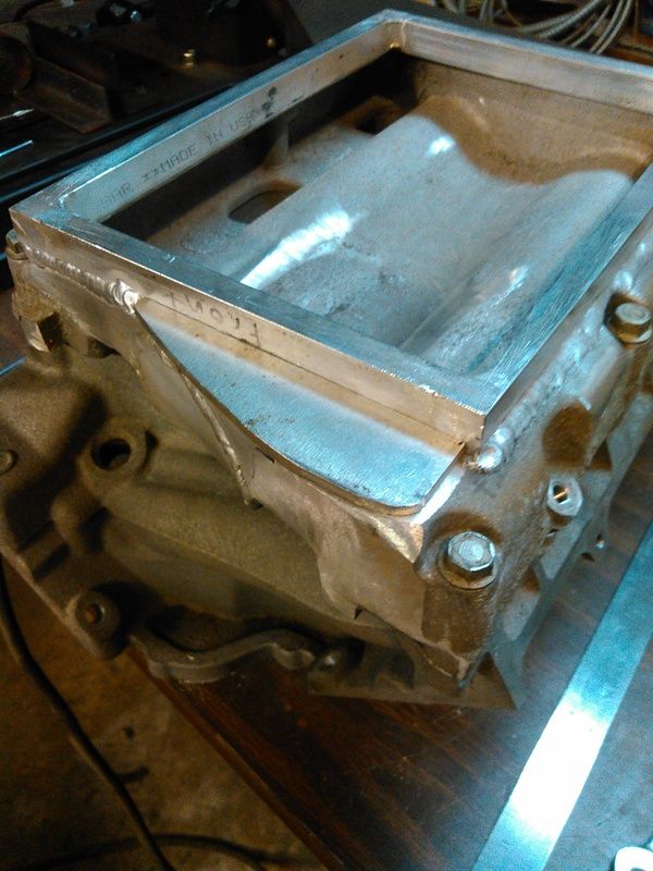
    It was +/- 40 thou, spent thirty minutes with a file and got it to this point:


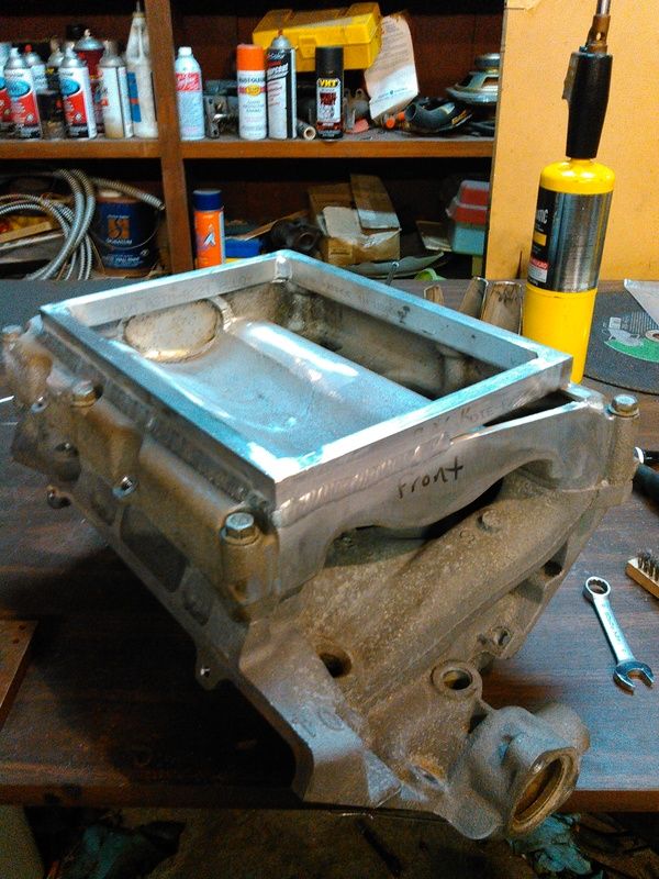
    Then I welded up this frame, it's 0.750" tall and 0.500" thick bar, and it actually came out pretty square. A little clean-up on the welding and it was ready to be welded to the top of the intake casting.


    Yes, I did fuck up. The sharp-eyed ones of you will notice that the intake says "front" and the frame says "back". No, it doesn't matter.

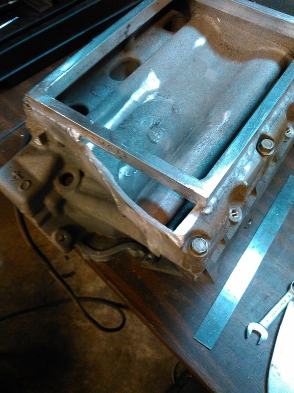
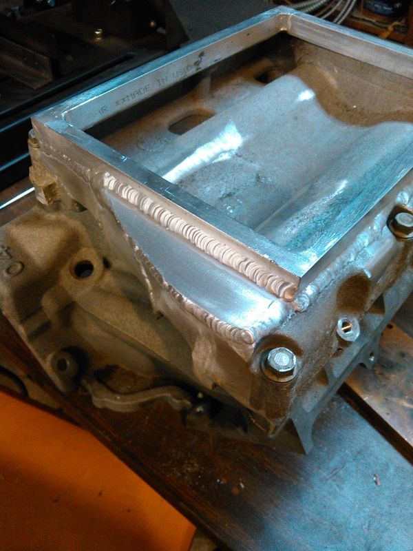
    The small hole in front was easily filled in, didn't take any photos. The bigger hole in the back I did take some photos of.


    I used some 0.213" thick plate that was in the big stack from page 1, it's thicker than the casting but I didn't have anymore of the 0.127" plate I used on the front. It'll be fine.


    When I'm not welding on shitty castings, I can go OK with the TIG with a little rum in me. None of that white rum shit, though.


    Now that the frame is welded on, I unbolted it from the lower intake manifold and measured how far it sprung during welding. The total out-of-flat was decent, pulled 0.013" total. That's totally workable, I'm gonna run it over to a buddy with a milling machine and have him skim it flat. Yeah, I *could* do it in the shop but the machined face on the bottom is slightly higher than the lowest part of the intake, so I'd have to find two slabs of plate that are parallel and flat, fit them both on the surface plate, and lap the intake against the plates...just more trouble than it's worth. Once the intake is flat and parallel then I'll start drilling and tapping the 20-something holes in the frame on top, that the supercharger plate will be bolted to. Once the plate is bolted down, I'll have to get the heads on the block and the lower intake manifold fitted, and get all the accessory drive bolted up, so I can get the supercharger drive pulley aligned and square. Once that's done and the super is fitted to the top plate, I can start on the headers.

    There's no exterior differences between the 3.4L aluminum-headed hybrid I'm building, and the 2.8L iron-headed boatanchor in the truck, aside from the accessory drive. Originally, when the 3.4L engine still had iron heads on it, the exhaust manifolds were identical. I've dummied up the headers in PVC on the truck, so I'm pretty sure I won't have to clearance the truck with the BFH later when I go to bolt the new engine into place. If I have to apply the BFH, well, then I have to apply the BFH.

  2. #92
    Fuel Injected!
    Join Date
    Jun 2015
    Age
    36
    Posts
    354
    OK, FTDI cable came in today, but I can't select 8192 baud, only 9600...argh. I KNOW this cable is an FTDI FT232RL, so what gives?

    Also, even with it passing the tunerpro test for cable, it will NOT connect to the ecu. I have ALL the system grounds and ecu grounds and the sensor grounds grounded. I have both battery feeds and the ignition feed powered. I have the serial ground connected to the system ground. I have the serial tx and rx connected to the serial line on the ECU. Still will not talk at all.

    What gives? I want to connect and talk to the ECU to find out what bin I need to be working with.

  3. #93
    Super Moderator
    Join Date
    Mar 2011
    Location
    Camden, MI
    Age
    35
    Posts
    3,026
    with the P66 V6 ADX loaded, correct COM port selected, there should be communications. if you had a clone chip instead of a legit FT232R(they're showing up in the strangest of places), then you would need to run an older driver package and they seem to work happily.

    don't suppose you have any status lights to tell you if it is sending/receiving data?
    1995 Chevrolet Monte Carlo LS 3100 + 4T60E


  4. #94
    Fuel Injected!
    Join Date
    Jun 2015
    Age
    36
    Posts
    354
    I bought directly from FTDI, it's not a clone. I have the P66 ADX loaded, the cable passes the test when not hooked up. once hooked up, it fails the test. it will not connect to the ECU, I choose connect and it will say "connecting..." but it never connects.

    All the wires marked "ground" in the file you gave me above are grounded, the Battery and Ignition wires have 12.6VDC to them, and the TX and RX wires are joined together to Serial Data. The ground from the USB cable is grounded to the rest of the ECM grounds. I rolled back to the older FTDI driver as detailed elsewhere on this site. Nothing has allowed it to connect to any of the four ECM's I've got here...two 4373 and two 6397, none of them talk. I have one each 4373 and 6397 that were pulled from running vehicles that I drove before pulling the ECM, so I know they're good.

  5. #95
    Super Moderator
    Join Date
    Mar 2011
    Location
    Camden, MI
    Age
    35
    Posts
    3,026
    hmm..... everything sounds correct. the cable passing when PCM unconnected and failing when PCM connected is normal.

    I don't believe there is any kind of "reasonable signal" requirement just for communications, though I've never run this particular PCM without most of the sensors connected.... maybe i'll throw together a quick harness and see if I experience the same.
    1995 Chevrolet Monte Carlo LS 3100 + 4T60E


  6. #96
    Fuel Injected!
    Join Date
    Jun 2015
    Age
    36
    Posts
    354
    I have the following hooked up and nothing else:

    A1 Sensor Ground (Black) To Ground
    A17 Sensor Ground (Black) To Ground

    B14 Battery Input (Orange) To +12.6V
    B15 Battery Input (Orange) To +12.6V

    B16 ECM Ground (Black/White) To Ground
    B32 ECM Ground (Black/White) To Ground

    B19 Serial Data (Tan) To TX/RX on the USB-5V TTL serial cable

    C1 System Ground (Tan/White) To Ground
    C17 System Ground (Tan/White) To Ground

    C3 Ignition Feed (Pink) To +12.6v

    That's all the wires I have connected, nothing else. I do have the oscilloscope watching the serial data line and I can watch the same data packet being sent over and over again, with no response from the ECM.

  7. #97
    Super Moderator
    Join Date
    Mar 2011
    Location
    Camden, MI
    Age
    35
    Posts
    3,026
    with just the 7 power/ground connections shown here connected to a 12.3 volt source, I'm showing a draw of 340mA. I need to find one of my bare UART-USB boards to get ALDL comms tested....

    1995 Chevrolet Monte Carlo LS 3100 + 4T60E


  8. #98
    Super Moderator
    Join Date
    Mar 2011
    Location
    Camden, MI
    Age
    35
    Posts
    3,026
    missed the part about the scope. the data being sent is for the DIC used on 94-95 grand prixs... it's sent out either 4 or 8 times a second(can't remember, it should be in the ALDL scheduler table though), so the PCM is attempting to communicate... that should rule out hardware problems, now it comes down to the USB adapter/software.
    1995 Chevrolet Monte Carlo LS 3100 + 4T60E


  9. #99
    Fuel Injected!
    Join Date
    Jun 2015
    Age
    36
    Posts
    354
    Technically I should be able to fire up a terminal emulator and listen in on that data, yes?

  10. #100
    Super Moderator
    Join Date
    Mar 2011
    Location
    Camden, MI
    Age
    35
    Posts
    3,026
    yes. I've used a few different programs in the past. a couple minutes ago, I used "OBD1 Sniffer 2", which I have no idea where it came from or who made it... works simple enough though, select a port, hit scan and it fills a text box with data. spit out this(I formatted it myself, it spits everything out raw. I want to say one of the aussie geniuses made a program that spit out the lines split up properly).

    F0 56 E4 D6

    0A 58 00 00 00 9E

    0A 58 00 00 00 9E

    0A 58 00 00 00 9E

    05 5F 00 40 00 3C 7B 00 00 00 00 01 A4

    0A 58 00 00 00 9E

    F0 56 E4 D6

    0A 58 00 00 00 9E

    0A 58 00 00 00 9E

    0A 58 00 00 00 9E

    05 5F 00 40 00 3C 7B 00 00 00 00 01 A4

    0A 58 00 00 00 9E

    F0 56 E4 D6

    0A 58 00 00 00 9E

    0A 58 00 00 00 9E

    0A 58 00 00 00 9E

    05 5F 00 40 00 3C 7B 00 00 00 00 01 A4
    that's exactly what I expect to see from this PCM with nothing happening...

    afterwards, I opened tunerpro, selected the COM port and started up a link that way.... connected within a second and gave an error-free stream. I even grabbed the VIN from this new unit, "1g1ld55m6sy237616". 2 codes get set(TPS low and trans temp), I was able to send mode 4 commands(target AFR) and see them effect commanded operation... cleared codes via mode 10, they stayed clear for a second and then reset(as expected).
    1995 Chevrolet Monte Carlo LS 3100 + 4T60E


  11. #101
    Fuel Injected!
    Join Date
    Jun 2015
    Age
    36
    Posts
    354
    scan 9495 V6 logger connects, and shows appropriate data-so the cable and at least the 4737 is working. I get a lot of this:

    Time=9:21:25 PM
    Vehicle Data Request-->-----
    0000000000
    00 00 00 00 00

    Then I slapped the shit out of the ECM out of frustration and got this:

    Time=9:21:26 PM
    Vehicle Data Request-->-----
    Shutup Request----E45608AE----
    Shutup Request----E45608AE----
    Shutup Request----E45608AE----

    Time=9:21:26 PM
    Vehicle Data Request-->-----
    Response: cs=80 Bad Checksum!
    Bad Response : E4 57 0104 c0 c0 c0 c0 c0 c0 c0 c0 c0 c0 c0 c0 c0 c0 c0 c0 c0 c0 c0 c0 c0 c0 c0 c0 c0 c0 c0 c0 c0 c0 c0.....c0 c0 c0 c0 c0Engine Request-->-----E4570100----
    Response: cs=78 Bad Checksum!
    Bad Response E4 56 0A BC E4 57 01 00 C4 C4 C4 C4 C4 C4 C4 C4 C4 C4 C4 C4 C4 C4 C4 C4 C4 C4 C4 C4 C4 C4 C4 C4C4 C4 C4 C4 C4.....C4 C4 C4 C4Actuator request-->-----F46204xx...-----


    Hopefully that comes through OK.

  12. #102
    Fuel Injected!
    Join Date
    Jun 2015
    Age
    36
    Posts
    354
    Got it! another good slap to the ECM and I noticed the Over Current light was lit on the power supply. Cranked up the current limit and now I have full comms, both directions.

    Sometimes stupid is just stupid.

  13. #103
    Super Moderator
    Join Date
    Mar 2011
    Location
    Camden, MI
    Age
    35
    Posts
    3,026
    huh... simple answers definitely aren't bad ones.

    I'm using a less sophisticated method(converted ATX power supply), my overcurrent protection kicks in for the 12V rail somewhere near the 20-amp mark. 340mA is actually a bit less than what I was expecting... my full bench is based around a 16149396, which is a single P4 processor unit and I want to say it draws something like 500mA with no loads.
    1995 Chevrolet Monte Carlo LS 3100 + 4T60E


  14. #104
    Fuel Injected!
    Join Date
    Jun 2015
    Age
    36
    Posts
    354
    I just registered at PCM-Hacking.net, maybe the flash tool they've got will flash these ECM's too?

  15. #105
    Super Moderator
    Join Date
    Mar 2011
    Location
    Camden, MI
    Age
    35
    Posts
    3,026
    nowhere near similar enough IIRC.... their flashable 3800 PCMs are(I think) single P6 units(running at I think a ~3.15MHz clock) with I think a lot of bank switching going on to access much larger calibrations.
    1995 Chevrolet Monte Carlo LS 3100 + 4T60E


Similar Threads

  1. 16172693 16184164 16184737 16196397 PCM Information P66 V6
    By RobertISaar in forum GM ECM - Bins - TunerPro Definition Files - Wiring Diagrams - Tuner Info!
    Replies: 5
    Last Post: 04-18-2014, 05:49 PM

Bookmarks

Posting Permissions

  • You may not post new threads
  • You may not post replies
  • You may not post attachments
  • You may not edit your posts
  •