


so, I'm blind. these images looked in-focus through the viewfinder of the SLR, turns out I really, REALLY need to go have my lens prescription updated. autofocus doesn't appear to like many-faceted reflective surfaces, so I had to go about it manually. combine that with a 1.8 aperture and things can get messy at times. these are the best of the groups that I shot.
all of the images should be in the same orientation as the mspaint outline, at least the chip-sides are. on the reverse side of the board, obviously there is going to be a horizontal flip, but it shouldn't be too difficult to figure out.


 Reply With Quote
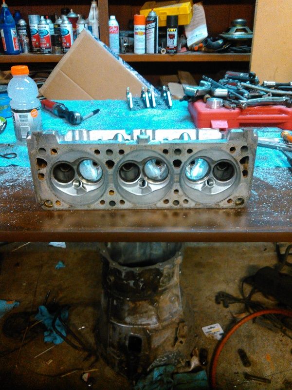


Bookmarks