

PE4/AN4 on pin 60 is grounded, would have to lift the pin on the MCU to get it into some circuitry. Can be done, though. Turns out that this is an analog input, though-I started looking for the wrong thing I think.


PE4/AN4 on pin 60 is grounded, would have to lift the pin on the MCU to get it into some circuitry. Can be done, though. Turns out that this is an analog input, though-I started looking for the wrong thing I think.
Originally Posted by Xnke
 i have channel 0 listed as "knock filter(output?)" something goes on with that channel in the code, but I don't know what. maybe i'll take another look.
getting this PCM to log a wideband is just the same as another MAP sensor... just need a free a/d channel on the E-side(there MIGHT be enough space on the T-side to pull off an A/D read/store and jump back to normal code, but it would be close) and a little bit of space, maybe 20 bytes or so. as long as the channel doesn't have a pull-up resistor the way that the temperature channels do, then they should have just a low-pass filter between the PCM connector pin and either the micro's pin or the mux chip's pin. could also do something out of the ordinary and setup the calibration to only use one O2 sensor(like a FWD application does) and run a wideband signal through a voltage divider and feed it into the "spare" O2 sensor a/d channel. someone on this forum did that with my recommendation and they had good results, I just can't remember any details of the project.
lifting pins wouldn't be too bad, be better if one of the other circuits were already connected to the PCM connector.
seeing how it may help, here's what I have for the a/d channels:
e-side: channel 6 appears to be a mux channel
0: knock filter(output?)
1: right/rear O2
2: left/front O2
3: TPS
4:
5: MAT
6: MUX
7: MAP
6.00: A/C pressure sensor
6.20: fuel pump volts
6.40:
6.60: ???? (transferred to T-side as T-buffer 7, LSB, only used for DTC86 testing, value above d25 sets code)
6.80: A/C evaporator temp sensor
6.A0: ???? (transferred to T-side as T-buffer 12, LSB, only used for DTC43 testing), knock sensor input?
6.C0: coolant temp
6.E0:
*6.60 may be connected to quad driver fault line?
t-side:
0: ???? (read but not used except for factory test?)
1: TPS
2:
3: MAP
4: Trans Fluid
5:
6: Battery Volts
7: PCS Sense
1995 Chevrolet Monte Carlo LS 3100 + 4T60E
Still can't figure this one out. Pin 60, A/D channel 4, goes into one of the inner layers of the board-it appears to be a four-layer board. It probably isn't actually grounded. I have located a pad on the lower side of the board that shows continuity, but it also shows continuity to pin 59, A/D channel 0. Channel 0, the one you have as a possible knock filter output, is an input-only pin, according to the MC68HC11F1 documentation. Must be the output of the knock filter going in to the MCU.
more stuff I need to investigate further, I'm guessing at channel 0 based only on what the code does with it. with 6.A0 also appearing as knock sensor related, I really don't know what to think.
1995 Chevrolet Monte Carlo LS 3100 + 4T60E
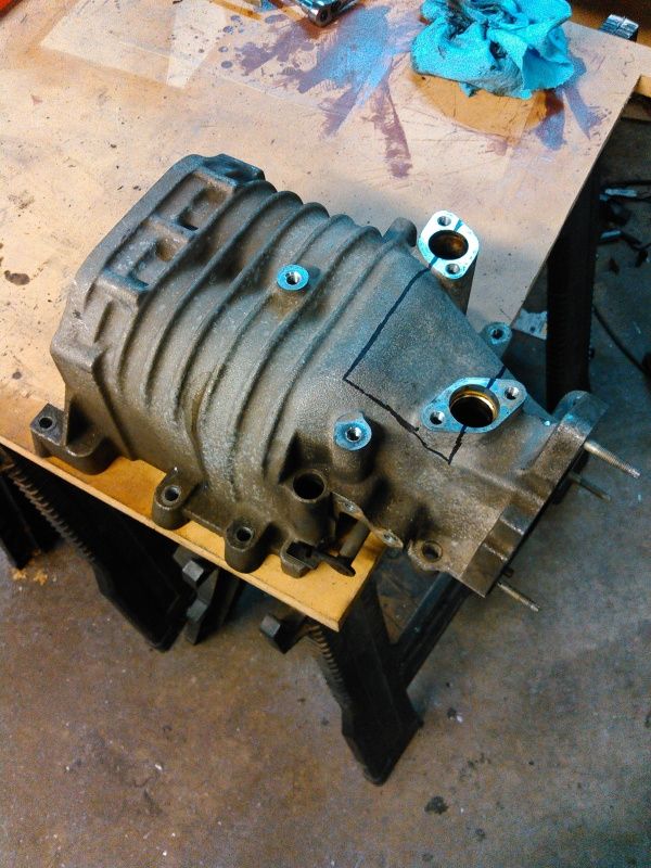
Picked up some PCM wiring harness connectors today at the parts yard, plus the forward lamp harness connector for a Camaro so I can not hack up the F-body harness as much. Also grabbed a MAP sensor from a supercharged Buick, as well as four more M90 blowers...I have enough blowers now for a while. All of them just need the coupler replaced in the snout, fresh oil, and they're good as new.
Also, my Northstar throttle showed up, complete with busted IAC...hoping the SFI IAC will fit down in its place. I don't want to buy another one if I don't have to.
Waiting on an intercooler core, 120mmx120mmx42mm, two-pass unit.
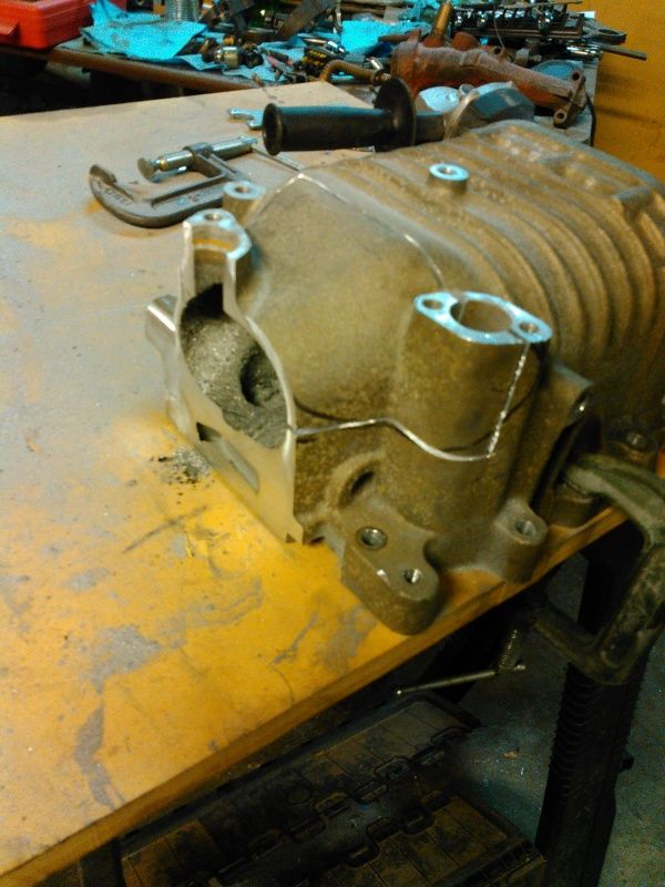
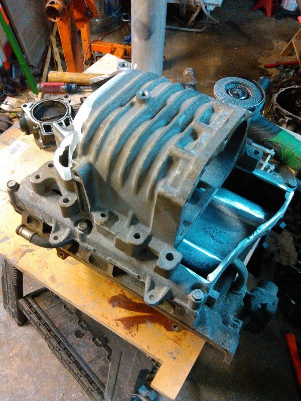
Tonight was spent reworking the supercharger case. Trimmed off the original throttle body flange, started opening up one side of the case.
Here's the case trimmed, marked out and starting to open it up:
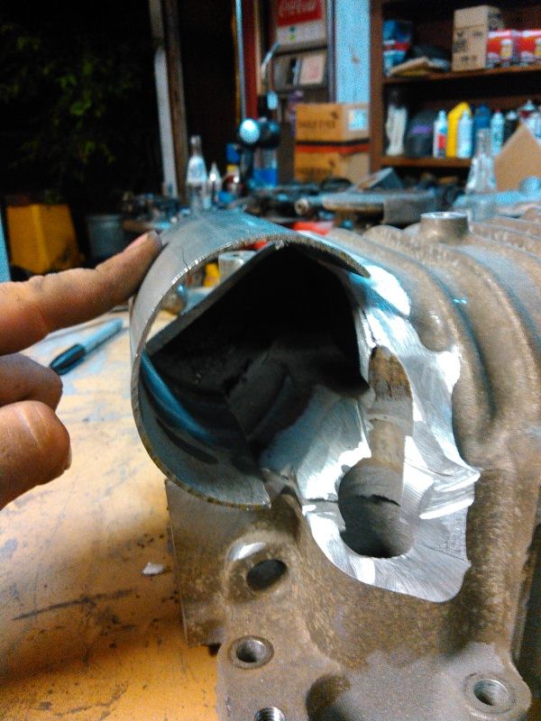
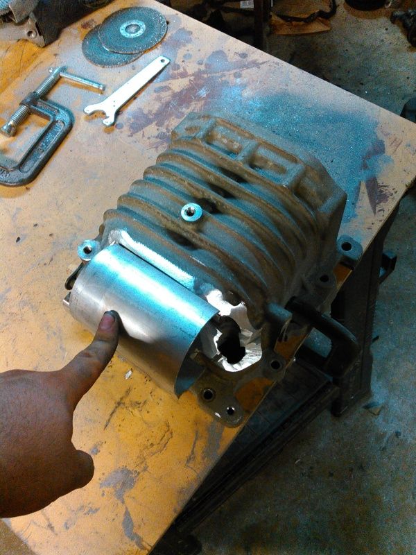
Started mocking it up with a section of 3" tubing, getting a feel for how things are going to work out. Will need a bit of welding to get things radiused correctly.
Another look:
Positioned on top of the upper manifold, trying to get an idea of how the throttle body will set. It's a 75mm unit from a Northstar V8.
A couple more hours has this fitted and fixed.
Did some more hunting around tonight in the ECM-There is no pin currently connected to the exterior of the ECM that is tied to Pin 60/AN4 of the E-side 'HC11. A LOT of pins have 5.6K or 9K resistance to that pin, though, which reaffirms my suspicion that it's grounded-as all unused analog input pins should be for good practice.
I don't have any method of currently flashing the PCM right now, haven't bought Winflash because to be honest, I don't really trust the TunerCATS website, and I don't have 50$ to drop on the Madtuner software right now. As soon as I do, I'll lift the AN4 pin on the auto ECM and see if I can twiddle the line, is there any indicator in Tunerpro that would tell me if I have the right pin?
 Posting Permissions

 Reply With Quote

Bookmarks