Results 1 to 15 of 349

Thread: Anyone worked with the 16196397 yet?

Hybrid View

Previous Post Previous Post   Next Post Next Post
  1. #1
    Super Moderator
    Join Date
    Mar 2011
    Location
    Camden, MI
    Age
    35
    Posts
    3,026
    i have a spreadsheet of what I'm referring to as "the" p66 v6 pinout.... I basically combined all of the p66 v6 applications into a single sheet and have them cross-referenced by application. it's been useful at times, like defining a/d inputs and outputs in the code that were otherwise unused in my application...

    you may find some use to it.
    Attached Files Attached Files
    1995 Chevrolet Monte Carlo LS 3100 + 4T60E


  2. #2
    Fuel Injected!
    Join Date
    Jun 2015
    Age
    36
    Posts
    354
    That list covered most of the other wires. I'm still curious as to a few of them but mostly as possibilities for use with the intercooler system-Could I use Trans Fluid Temp to toggle TCC Control into an ON/OFF state, therefore allowing me to cycle the intercooler water pump based on intercooler water temperature?

    What's more, if I CAN do something similar, that makes this a very powerful unit indeed-There are a lot of inputs/outputs that could be repurposed.

  3. #3
    Super Moderator
    Join Date
    Mar 2011
    Location
    Camden, MI
    Age
    35
    Posts
    3,026
    hmm..... with both of those being on the T-side, not really able to patch in that kind of a function. might be able to abuse the existing calibration items to do it though.

    alternatively.... the a/c temp sensor(only ever used on f-body calibrations) is on the e-side and is also already setup with a pullup to 5V, and would be otherwise unused for your application. most of the existing code concerning it could be kept as-is. you have a couple outputs you could choose from on the e-side as well, depending on what equipment you plan to keep on the engine. E-side controls:

    all 3 EGR solenoids
    a/c clutch
    CCP
    AIR pump
    and an unused circuit on quad-driver U34, should control pin B5.
    1995 Chevrolet Monte Carlo LS 3100 + 4T60E


  4. #4
    Super Moderator
    Join Date
    Mar 2011
    Location
    Camden, MI
    Age
    35
    Posts
    3,026
    just now have time to crack open my actual 6397.... there are a few differences going on compared to the 93 3.1/3.4 unit. a resistor missing/added here and there and even changes to the board itself. i'll need to check this out a bit further and make sure nothing too critical changed.

    the same ICs all around(some part number changes at times.... same apparent function at least), i'll try and summarize the changes I see. red implies something was removed on the 6397 compared to the 93 unit, green is added.

    E:
    2: a pair of missing resistors, both part of the same circuit. 1 added resistor, a 10K pulling something up to 5V.
    3: underside of large, 110 ohm resistor that was moved slightly.
    4: showing 2 again, but now with a couple of caps/resistors removed from the connectors. also to the right are the addition of some solder pads, but they're not populated on this board....
    5: a pair of resistors and a cap(all part of the same circuit) removed.
    6: removed diode
    7: showing where the resistor was moved to.
    8: 3 resistors and a cap(same circuit), all removed.

    T:
    1: removed cap from connector, a pair of resistors(same circuit), removed. the cap they connect to on 3 is changed to a shorting link as well.
    2: pair of connector caps removed.
    3: showing where the changes noted from 1 continue.
    5: these two components(fairly certain they're diodes) are removed. the upper was used for pin B17(unused AFAIK), lower for pin B5. pin B5 still appears to be connected everything otherwise, so it is still capable of being used, but it doesn't have what I'm thinking is a flyback diode to protect it should it be used to drive a relay or solenoid without a flyback diode integrated into them. they have a "4801" marking on them, but I don't think they're a 1N4801...
    6: we lose quite a few diodes... they don't appear to cause any loss of function, seems like they were more for circuit protection than anything else.

    ......... and that's it.

    i'll investigate a bit more on the changes mentioned, but there doesn't appear to be a whole lot of difference between the 93-only unit and the '6397...
    Attached Files Attached Files
    1995 Chevrolet Monte Carlo LS 3100 + 4T60E


  5. #5
    Fuel Injected!
    Join Date
    Jun 2015
    Age
    36
    Posts
    354
    I plan to keep the A/C, but not the temperature sensor for the A/C...I don't have the little box+thermistor for that. It's a manual truck, so the list of stuff I don't intend to keep or isn't going to be used as per OEM, that was fitted somewhere on the original system, is as below:

    A/C Evaporator temperature (Pin A3)
    Transmission Fluid Temperature (Pin A32)
    Secondary Air Injection Control (Pin B3)
    Evap Purge Solenoid Control (Pin B4)
    EGR #1 Control (Pin B11)
    EGR #2 Control (Pin B12)
    EGR #3 Control (Pin B13)
    Passkey II (Pin C23)

    Auto Trans stuff that I don't need/might not even be there on 6397:

    Shift Solenoid A (Pin A11)
    Shift Solenoid B (Pin A12)
    TCC PWM Control (Pin A13)
    TCC Control (Pin A15)
    3-2 Downshift Solenoid Control (Pin A16)
    PRNDL A (pin A21)
    PRNDL C (Pin A23)
    2nd gear start lamp control (Pin B18)
    PCS High (pin C5)
    PCS Low (Pin C6)
    2nd Gear Start (Pin C10)

    I am torn on the Cruise Control stuff-I am not sure if it's usable, as my truck didn't have cruise control fitted and I am not sure how manual transmission cruise control would work, even if I did pull all the cruise junk off of another car.

    Hopefully I'll get the ECM booted up on the bench in a few hours and see what I really have here.

  6. #6
    Super Moderator
    Join Date
    Mar 2011
    Location
    Camden, MI
    Age
    35
    Posts
    3,026
    E:
    2: added resistor brings U10, pin 5 up to 5V... the two missing resistors appear to have been used in the same circuit, perhaps some logic was inverted?
    4: connector changes effect: pin C26(never used). runs over to the missing components from image 8. pin 22 is related to the missing resistors from image 2.
    5: U10 pin 2 and 5 interact here, which means it also is related to the change from image 2.
    6: diode was connecting analog channel 5(IAT) with the a/d reference voltage... so if for whatever reason IAT was above 5 volts(and whatever the diode's forward voltage at x mA is), the a/d converter would start having issues.
    8: covered by the images before it.

    seems there were only two major changes here, with supporting modifications done alongside. the diode on IAT to Vrh is strange....


    T:
    1: A28 effected by connector change. related to missing resistors from same image that causes a/d channel 5 to be connected to 5V(or ground???) via shorting link? not sure what to expect here... the circuit seems pretty broken up due to the removed resistors.
    2: B17 and B5 effected by connector change. both are outputs(B5 from the quad driver, B17 the surface-mount driver).

    that should cover it...

    some creative cutting/soldering may be necessary to add too much more than what is already here.... I'm thinking since the E-side analog4 is right on the corner of the chip(and even more unused than before), I'd just lift the pin and attach it to some add-in your own filtering/pullup/down circuitry rather than reworking. could either keep it as one channel or snake out and attach the existing mux A, B and C circuits to another mux and end up with 8. then, start cutting pins at the connectors and you'll have more a/d circuits than you'll know what to do with.
    1995 Chevrolet Monte Carlo LS 3100 + 4T60E


  7. #7
    Fuel Injected!
    Join Date
    Jun 2015
    Age
    36
    Posts
    354
    Argh. Turns out my "FTDI" USB to TTL cable that I ordered weeks ago and just now got around to plugging in is a Prolific clone. No good.

    Ordered another from another supplier, hopefully it'll work out better. Still haven't been able to connect to an ECU yet.

  8. #8
    Fuel Injected!
    Join Date
    Jun 2015
    Age
    36
    Posts
    354
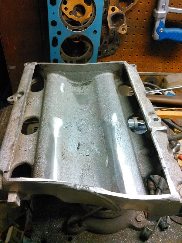
    While I wait on my *hopefully* FTDI branded cable, I did some more work on the intake manifold.

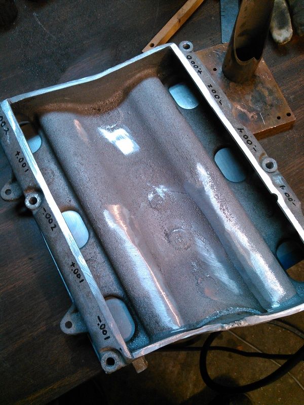
    First thing to do is get it cleaned up a bit and start measuring how far off I was with the angle grinder.


    It was +/- 40 thou, spent thirty minutes with a file and got it to this point:


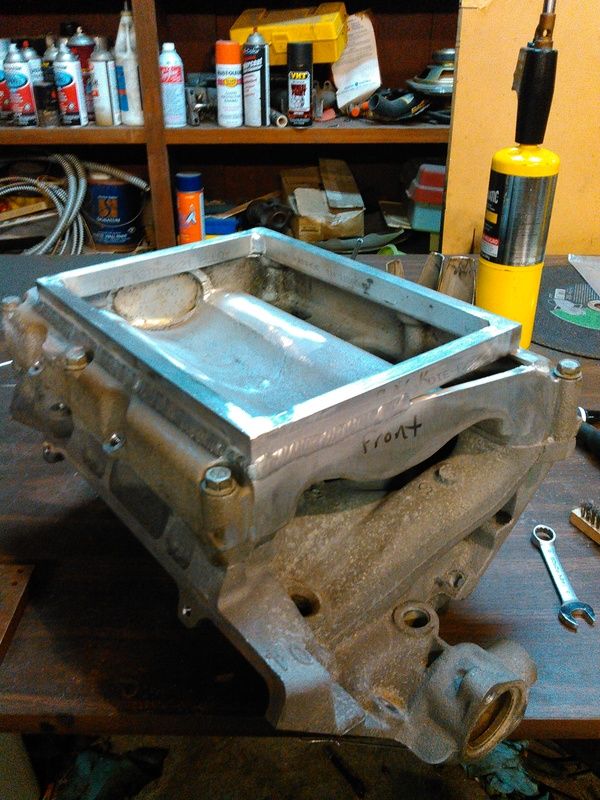
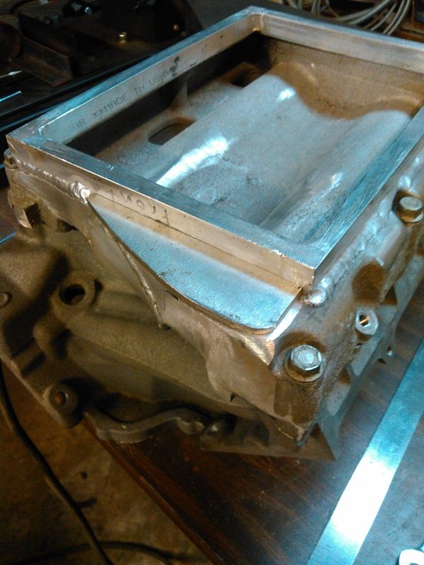
    Then I welded up this frame, it's 0.750" tall and 0.500" thick bar, and it actually came out pretty square. A little clean-up on the welding and it was ready to be welded to the top of the intake casting.


    Yes, I did fuck up. The sharp-eyed ones of you will notice that the intake says "front" and the frame says "back". No, it doesn't matter.

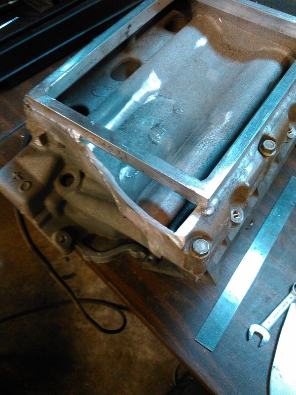
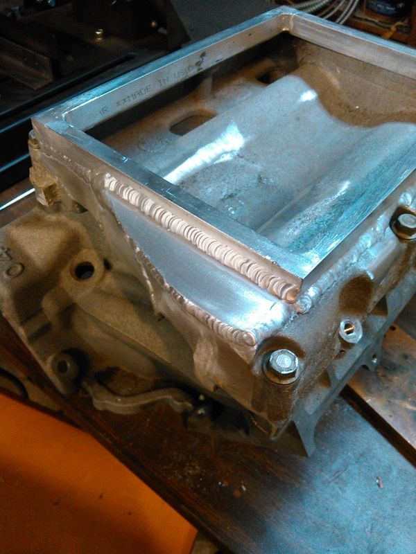
    The small hole in front was easily filled in, didn't take any photos. The bigger hole in the back I did take some photos of.


    I used some 0.213" thick plate that was in the big stack from page 1, it's thicker than the casting but I didn't have anymore of the 0.127" plate I used on the front. It'll be fine.


    When I'm not welding on shitty castings, I can go OK with the TIG with a little rum in me. None of that white rum shit, though.


    Now that the frame is welded on, I unbolted it from the lower intake manifold and measured how far it sprung during welding. The total out-of-flat was decent, pulled 0.013" total. That's totally workable, I'm gonna run it over to a buddy with a milling machine and have him skim it flat. Yeah, I *could* do it in the shop but the machined face on the bottom is slightly higher than the lowest part of the intake, so I'd have to find two slabs of plate that are parallel and flat, fit them both on the surface plate, and lap the intake against the plates...just more trouble than it's worth. Once the intake is flat and parallel then I'll start drilling and tapping the 20-something holes in the frame on top, that the supercharger plate will be bolted to. Once the plate is bolted down, I'll have to get the heads on the block and the lower intake manifold fitted, and get all the accessory drive bolted up, so I can get the supercharger drive pulley aligned and square. Once that's done and the super is fitted to the top plate, I can start on the headers.

    There's no exterior differences between the 3.4L aluminum-headed hybrid I'm building, and the 2.8L iron-headed boatanchor in the truck, aside from the accessory drive. Originally, when the 3.4L engine still had iron heads on it, the exhaust manifolds were identical. I've dummied up the headers in PVC on the truck, so I'm pretty sure I won't have to clearance the truck with the BFH later when I go to bolt the new engine into place. If I have to apply the BFH, well, then I have to apply the BFH.

Similar Threads

  1. 16172693 16184164 16184737 16196397 PCM Information P66 V6
    By RobertISaar in forum GM ECM - Bins - TunerPro Definition Files - Wiring Diagrams - Tuner Info!
    Replies: 5
    Last Post: 04-18-2014, 05:49 PM

Bookmarks

Posting Permissions

  • You may not post new threads
  • You may not post replies
  • You may not post attachments
  • You may not edit your posts
  •