Results 1 to 15 of 349

Thread: Anyone worked with the 16196397 yet?

Hybrid View

Previous Post Previous Post   Next Post Next Post
  1. #1
    Fuel Injected!
    Join Date
    Jun 2015
    Age
    36
    Posts
    354
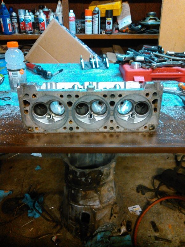
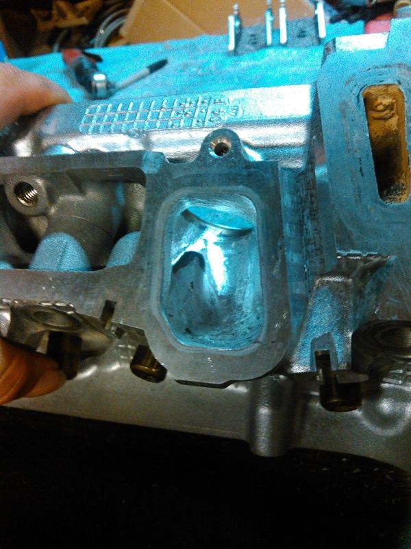
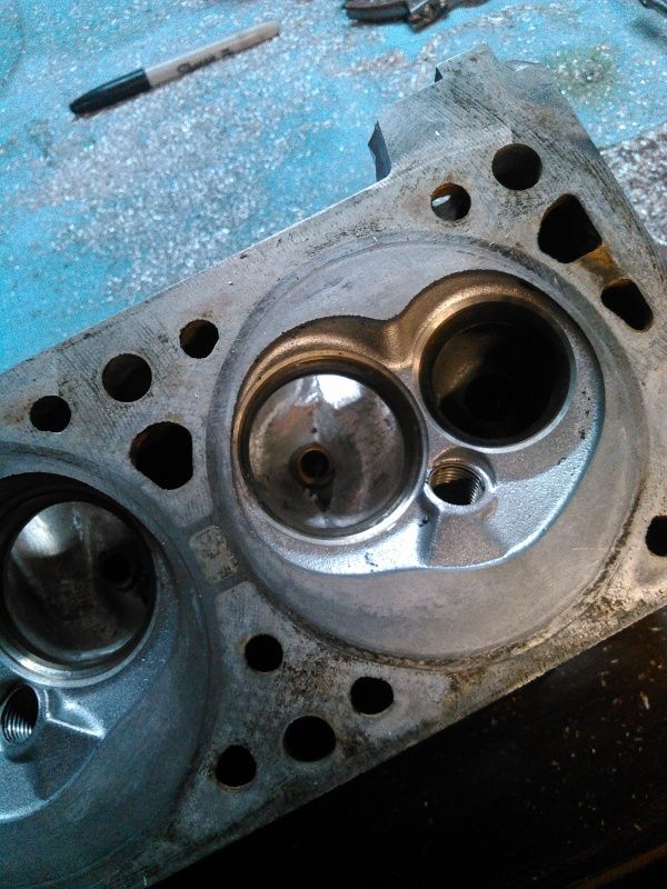
    This is an awesome amount of data. I am going to try to trace through my 6397 here and find the A/D outputs that you have listed, see if I can lift the pullup/pulldown resistors and reconfigure it as a "normalized" 0-5V standard analog input for WBO2 monitoring. I just got home from the gulf coast so I'll get those comparison shots of the internals of a 4737 and 6397 today and get them posted up here, hopefully that helps some.

  2. #2
    Fuel Injected!
    Join Date
    Jun 2015
    Age
    36
    Posts
    354
    Been going over the one stripped apart on my desk, here's what I am seeing:

    IRF9395 INJECTOR DRIVERS
    8.388MHZ CRYSTAL
    MISSING: U14 AND 2 LARGE TRANSISTORS
    missing transistor closest to knock filter controls pin C5, other controls C6, these are PCS high and PCS low. <--Pretty sure these are missing on my 6397 as well.

    6811 A/D:
    0 - battery volts
    1 - right/rear O2
    2 - left/front O2
    3 - TPS
    4 - pin A28(1K pulldown, 10K isolation)<--This is totally workable.
    5 - IAT
    6 - a/d mux chip's output
    7 - MAP

    Got anything to get me closer to locating the 1K pulldown and 10K isolation resistors for AD4? I am looking, hunting, probing, and am not seeing yet. It has been years since I did this level of hunt-and-peck, I've lost my eyes.

  3. #3
    Super Moderator
    Join Date
    Mar 2011
    Location
    Camden, MI
    Age
    35
    Posts
    3,026
    some stuff is in non-sensical locations... most of them are channels have their R/C filtering components fairly close together though, when you find one, you'll find all of them. I seem to remember a cluster of caps/resistors for the e-side a/d channels on the other side of the board, right under/around the 6811. I did all of the e-side stuff first though.... I can vividly remember where everything is for the t-side stuff, but E is a little shaky.

    A28 does seem like it would work without any changes. A4 on the mux'd A/D circuit looks like it should also work.

    I'll work on pulling the best of the images I have along with a mspaint masterpiece of my chip name assignments.
    1995 Chevrolet Monte Carlo LS 3100 + 4T60E


  4. #4
    Super Moderator
    Join Date
    Mar 2011
    Location
    Camden, MI
    Age
    35
    Posts
    3,026
    so, I'm blind. these images looked in-focus through the viewfinder of the SLR, turns out I really, REALLY need to go have my lens prescription updated. autofocus doesn't appear to like many-faceted reflective surfaces, so I had to go about it manually. combine that with a 1.8 aperture and things can get messy at times. these are the best of the groups that I shot.

    all of the images should be in the same orientation as the mspaint outline, at least the chip-sides are. on the reverse side of the board, obviously there is going to be a horizontal flip, but it shouldn't be too difficult to figure out.
    1995 Chevrolet Monte Carlo LS 3100 + 4T60E


  5. #5
    Super Moderator
    Join Date
    Mar 2011
    Location
    Camden, MI
    Age
    35
    Posts
    3,026
    i can't figure out how to reasonably format the text in the posts either, so here is the .txt version. should be a little easier to read considering how many Tabs I put into my documents.
    1995 Chevrolet Monte Carlo LS 3100 + 4T60E


  6. #6
    Fuel Injected!
    Join Date
    Jun 2015
    Age
    36
    Posts
    354
    Back in the workshop tonight.

    Since the heads needed a valve job anyway, I set the flow bench up in %Flow and started working on the intake port. I still don't have my calibrated venturis made, so I can only measure gains against the fixed orifice plate. I have what the stock heads flowed on a different bench on a different day, but using a clean valve and clean stock port, on the factory valve job, I set a baseline, then worked the port to produce a fair increase in flow while only removing 2.1CC's of material. Low-lift flow didn't suffer any, flow at 0.250" lift picked up 14%, and flow at 0.500" lift picked up 16%. Port is a little howly at 0.500" lift. At 0.550" lift it is louder, same pitch, and flow only picks up about 4% over stock. At least it didn't loose any! Stock, the port was quiet at all lifts. I did not open the gasket face of the port up any at all, MCSA is unchanged from stock. Mostly reduced and re-shaped the valve guide boss, the rest of the port just needed a little cleaning up of casting flaws around the valve seat. Port hasn't been cartridge-rolled yet, so it's right off the carbide. I didn't nick up the stock seats, so this is all on a stock valve job so far. The combustion chamber needs some attention, lots of sharp edges left over from the factory seat cutter, basically a sharp ring all the way round the valve on the intake. Exhaust valve has a nice smooth cut though, on most of the chambers. I will clean off the sharp edge and that's it for the chamber.


    Found out that Comp Cams PN 26986 springs will fit the stock seats/seals/retainers, which is nice. They seem to be a universal spring with a 1" ID and 1.45" OD at the base, and with the 0.650" ID at the top, LS1-style retainers work too. PAC-1286 is the same spring, Scorpion Racing SRP-1286 is the same spring. I am calling PSI springs tomorrow to see what they got. The Comp springs are slightly over budget at this point, but something will have to happen, as the stock springs checked out all over the place for spring rate...out of 12 springs, the deviation from mean was 22%.

    I asked about the resistors as I am trying to work out how they're arranged...is it a series 10K with a 1K pulldown on the 68HC11 side or a 1K pulldown on the outside-world side?

  7. #7
    Super Moderator
    Join Date
    Mar 2011
    Location
    Camden, MI
    Age
    35
    Posts
    3,026
    going off of memory, it's going to be something like:

    sensor signal wire->pulldown resistor->isolation resistor->A/D pin

    most of the a/d channels have a cap after the isolation resistor to form a RC low-pass filter, but I don't believe that I found one with the A28 circuit, but I did with the A4.
    1995 Chevrolet Monte Carlo LS 3100 + 4T60E


Similar Threads

  1. 16172693 16184164 16184737 16196397 PCM Information P66 V6
    By RobertISaar in forum GM ECM - Bins - TunerPro Definition Files - Wiring Diagrams - Tuner Info!
    Replies: 5
    Last Post: 04-18-2014, 05:49 PM

Bookmarks

Posting Permissions

  • You may not post new threads
  • You may not post replies
  • You may not post attachments
  • You may not edit your posts
  •