Results 1 to 15 of 349

Thread: Anyone worked with the 16196397 yet?

Hybrid View

Previous Post Previous Post   Next Post Next Post
  1. #1
    Super Moderator
    Join Date
    Mar 2011
    Location
    Camden, MI
    Age
    35
    Posts
    3,026
    A4 should be the E-side's mux'd A/D channel 3
    A7 should be the E-side's mud'x A/D channel 2
    A28 should be the T-side's A/D channel 5

    A7 already being on the e-side, you'll just have to break a small patch in somewhere, I don't believe it to be read/stored in the factory code, but it has been a while since I've looked at the non-used a/d channels.

    C19 and C24, no idea, I don't have any notes about them, so I may have considered them dead ends as well.

    C22 and C26 possibly being pulsed sensor inputs is possible, even likely. the last time I had one of the P66 V6 PCMs open, I did notice some discrete components missing from some of the C connector's circuits that looked like they may have been used as such, but I either didn't investigate further or didn't find anything of particular interest. since both the E-side and T-side TIC channels are already completely used, I don't know what else could have been present, unless it doesn't go to the 6811s directly... or at all?
    1995 Chevrolet Monte Carlo LS 3100 + 4T60E


  2. #2
    Fuel Injected!
    Join Date
    Mar 2013
    Posts
    1,478
    Thanks for the help.
    I did make some experiments and here is what I found

    On Tside

    #0 AD 252 PIN A31 coolant
    #1 TPS AD 251
    #2 Open state ad counts $c2 which is about 4v I measured all the pins on the knock filter and all showed 0v ??3rd pin knock filter??
    #3 MAP AD DB
    #4 TRANS TEMP AD 124
    #5 PIN A28
    #6 Battery AD BA
    #7 PCS current 197

    ESIDE
    $000 AD IGN VOLTAGE 185
    $100 L02 AD 144
    $200 R02 AD 155
    $300 TPS AD 24e
    $400 PIN A28
    $500 MAT AD 263
    $6xx
    $700 MAP AD 182

    $600 AC PRESS 288
    $620 FUEL PUPM AD 19b
    $640 PIN A7
    $660 MUX AD 188 PIN A4
    $680 AC EVAP AD 187
    $6A0 KNOCK SENSOR AD 186
    $6C0 Coolant AD 264
    $6E0 No PINS INTERNAL CONNECTED shows $00 at open state Poss flash Vpp voltage

    I got the voltage at pin a7 and my plan is to log 0-90 ohm fuel sender. Than I will use one of the PWM channels(at Pin B3 or B5) to drive a gauge.
    My current problem is that I got very low ad resolution. I got $13 ad counts at 90 ohm and $01 at 20 ohm. Do you have any idea how to get higher resolution?
    Maybe swap some of the resistors on the board.

    I am almost sure that pin c22 and c26 goes to the third processor on e-side board. It is one of the big chips. What i know is that it has some build in rom. Share memory address with eside 68hc11 at around 3bb0 -3fbc. At these addresses the 2 processor exchange data. Maybe the third processor uses some of these memory region as its own ram, I can see only the references from 68hc11 in the disassembly.

  3. #3
    Super Moderator
    Join Date
    Mar 2011
    Location
    Camden, MI
    Age
    35
    Posts
    3,026
    your notes match most/all of mine, differences may be explained by my primary study of the 93 only unit.... I wasn't expecting much change with the 94-95 PCMs, but there does appear to be some.

    with pin A7 only having a 909-ohm pullup to 5V(this may be specific to the 93 unit, you'll want to verify) and attempting to use the 0-90 ohm range of the fuel level sender as a voltage divider, range will be problematic. you'll either need a pullup with much less impedance or use a different sender, like what was used on most ~97-up applications, should have a 50-250 ohm range IIRC. not sure which is more feasible for your application. I've run stuff like this through Falstad's circuit simulator(link) to get a good idea of what to expect and to prototype to some degree.

    the "3rd processor" could be one of 3 possible chips the microcontroller has its address lines connected to. the "37414" has all of the address/data lines directly connected, the 16126532 has all directly connected but A10, which is connected to I believe a logic gate(P31AB 47816). the 56597 has all data lines, but only A0-A3 connected(16 addresses), though the microcontroller's CSGEN circuit is connected to pin 48 of that chip. may be something interesting going on there. CSIO1 and CSIO2 are both connected to the 37414 chip(pins 43 and 42 respectively).

    that address range is similar/identical to the "P4 timer chip" as found in slightly older PCMs, which is essentially an auxiliary input/output controller, it acts on data sent from the PCM and can return data to it as well when requested. if there were more pulsed inputs, that is certainly where they would end up.
    1995 Chevrolet Monte Carlo LS 3100 + 4T60E


  4. #4
    Fuel Injected!
    Join Date
    Jun 2015
    Age
    36
    Posts
    354
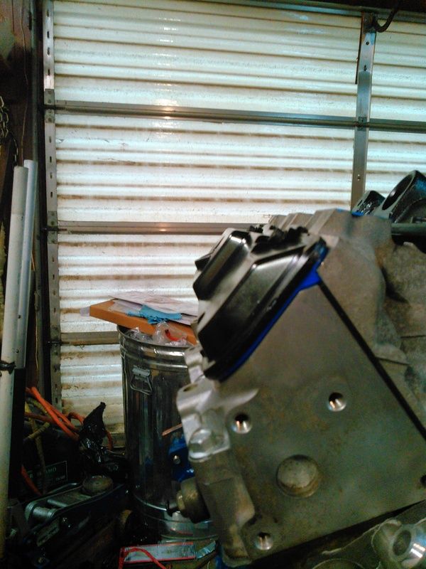
    Overkilled the shit out of a valve cover notch tonight. Might have to grab another valve cover next time I'm in the yard and do it over, but it's purely cosmetic at this point. The rocker arms have plenty of clearance.

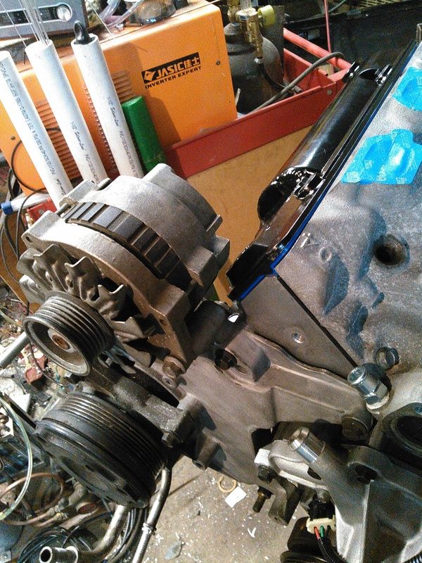
    This is a Gen2 valve cover-it doesn't *really* fit on the head. The two bottom valve cover bolts do not line up without cocking things all stupid, and they use a different style of bolt to hold them down. They DO clear the alternator, though.


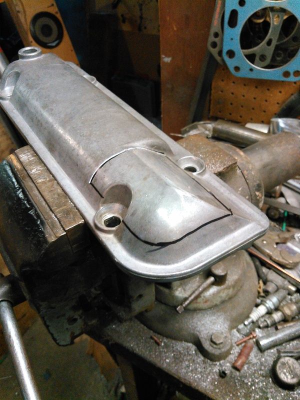
    This is the un-modified Gen3 valve cover, before I started chopping. The black cut line would make it the same height as the Gen2 cover.


    Well, now it clears the alternator....I didn't realize at the time I was marking it up that I was taking a BIG chunk. Oh well, it's painted black, and I can't see it from the driver's seat.


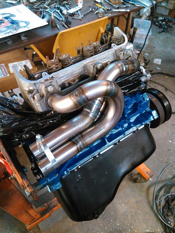
    Another gratuitous header shot-this time they're on the engine. I still haven't done much with the other side, yet.


    Maybe more tomorrow.

  5. #5
    Fuel Injected!
    Join Date
    Mar 2013
    Posts
    1,478
    I dig deep into the board of 98 pcm and found it has 243 ohm resistor, vs 909 ohm on the 94 board. They are of similar size and likely 0.75w. Everthing else is aranged identical with 10k isolation.
    The 98 pcm uses the newer style sender with 50-250 ohm sender, and with that resistor it goes upto to 2.5v. I will have to live up with 0-90 ohm, the low resolution and do some interpolation.
    Also test the pwm channel at pin b5 with mode 4 command. It will work perfect for my application.
    The output register of pin b5 is located at word_106c on eside. I wonder about the first byte of the pwm register, the second is the duty cycle, so I guess the first will be frequency. Any ideas how to manipulate it and what are the limits.
    When I am done with this will test some 64kb chips. Pin a15 on the t flash chips is grounded. Is the corresponding pin on the processor connected to something or is left open? First I will test with pin left open. Than if it doesn`t work I will try to destroy the board with some solder work.

    Xnke, You have great fabriaction skills. That headers look so sweet. How much is the estimate for the power output?

  6. #6
    Super Moderator
    Join Date
    Mar 2011
    Location
    Camden, MI
    Age
    35
    Posts
    3,026
    with a 243 ohm resistor and a 0-90 sender, you would have a ~1.35 volt range.... you could almost repurpose the op-amp that is used to amplify the O2 sensor signal, they're setup to operate as voltage multipliers of 4.5. a 330 ohm pullup resistor and O2 amp(or equivalent) would bring you to a ~4.8 volt range while retaining the 0-90 ohm sender.

    I'm not sure what the first byte of those registers will do, the ones that are taken care of via the P6 timer chip use the first byte for frequency(selectable between the classic 8, 16, 32, 64 and 128Hz used with the P4), but that address range isn't taken care of by the P6 timer AFAIK. I'm sure it's frequency but I'm not certain of how it is controlled yet. manipulating it may require playing a bit with the code, I only see 1 place in the code where the first byte is written for most compared to just the LSB being updated in most instances.

    the 6811's A15 runs to a few different places, I'm not sure where the best place to latch into it would be though. you'll also then have to somehow arbitrate between the various chips that would respond to reads/writes at whatever address. I'm not sure if just avoiding placing code/calibration in those areas will be sufficient.
    1995 Chevrolet Monte Carlo LS 3100 + 4T60E


  7. #7
    Fuel Injected!
    Join Date
    Jun 2015
    Age
    36
    Posts
    354
    I figure between 280 and 310HP, all told.

    Just cleaned the screen on my welding coolant pump and it started leaking on me...grrrrr!

Similar Threads

  1. 16172693 16184164 16184737 16196397 PCM Information P66 V6
    By RobertISaar in forum GM ECM - Bins - TunerPro Definition Files - Wiring Diagrams - Tuner Info!
    Replies: 5
    Last Post: 04-18-2014, 05:49 PM

Bookmarks

Posting Permissions

  • You may not post new threads
  • You may not post replies
  • You may not post attachments
  • You may not edit your posts
  •