Not sure what pump you have but if you look at the pictures in the link Mark posted you can see the black hose going to the jet pump.


Not sure what pump you have but if you look at the pictures in the link Mark posted you can see the black hose going to the jet pump.

that configuration seems fairly different from an lt1 pump

Maybe this will helpOriginally Posted by steveo

that flow diagram is very helpful.
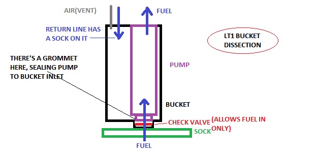
after taking one apart, i realize now that the lt1 factory pump bucket is way different.
there's no siphon pump or alternate inlet; only a single check valve and grommet that feeds the pump right from the sock. it's basically just a pump cooler/silencer. there's no way i can see for the pump to even draw from the bucket itself.
The siphon jet is at 2 and 3 the action of the fuel being circulated creates the low pressure zone that creates the siphon effect.
not in an lt1 sender, though. there is no 2 and 3. the pump grommets into a hole that goes right into the sock. there's no way for the pump to draw fuel from the bucket.
Ahh ok thought that pic was of a LT1 unit I'll have a look at the the spare I pulled when I got ours for us and see if i can figure it out. Might just be the return line does the job of keeping it filled.
yes; the bucket is always kept filled by the return line, however since the pump inlet is completely sealed to the filter sock and check valve tube via a grommet, the fuel in the bucket can't be used to feed the pump, only to cool it. the bucket is vented and not sealed..
The bucket came from a 1997 Regal GS s/c which has a different attachment to the fuel tank than the 2000 Impala LS undergoing the L67 swap. Impala has lock ring and wide black grommet to seal the FP module to the tank. The Regal has the snap ring and a blue O-Ring to seal the unit. By using the upper part from the Impala and the lower parts from the Regal, this should work for my application. The Impala has the fuel tank pressure sensor mounted to the FP module next to the fuel pump and sender wiring. The Regal has the tank pressure sensor located somewhere else. I hope this works - if anyone can see any reason why it won't, speak up. The idea for this comes from Greg's fuel pump thread. Thanks Greg!
L67 swap in progress - 2000 Impala LS
I had a handle on life once, then it broke off!
steveo
I have a 77 crew cab dually with the old tanks. I researched this while @ GM proving grounds with all aspects. From making the cut to the tank to using a SS external tank fed by the mechanical pump with return line. The ss tank would house the elec pump for my EFI BB Az Spd intake ect.... After talking to a few real smart gearheaded engineers AND some not engineer but gearheads ALL TOLD ME NOT TO CUT THE TANK and alter the opening. Why? In the event of a crash, side saddle tank OR NOT, you do not know if a solder joint that is even bolted with SS bolts will hold gas at over 7 lbs per gallon times the full tank in the crash. In stead I elected to take a 89 F-CAr tank unit (Having 4 lines) and use it in a 1987 Truck TBI tank put in my 1977 body. The extra line in the F-car sending unit is for tank venting to an external pressure vent when the tank pres rose greater then 4 PSI in the F-car. I use it as a fill line from the other stock tank with an external elec pump,
The crash lab boys looked at me like I was crazy. The SS extra tank with a mechanical pump feeding the SS tank, would generate so much VAPOR they calculated I would need about 4 big canisters. SS draws heat and holds it then transfers it to the liquid. You F-Car is a FUEL HEATER AS WELL...... My 2 1/2 cents
 Posting Permissions

 Reply With Quote
Bookmarks