Page 3 of 4 FirstFirst 1234 LastLast
Results 31 to 45 of 57

Thread: '7747 Flash Chip Conversion (27SF512)

  1. #31
    Super Moderator dave w's Avatar
    Join Date
    Feb 2011
    Posts
    6,264
    Quote Originally Posted by joegreen View Post
    I am going to do this instead of using the g2. I got a burn1 for $32 and am making my own cable. Maybe i can get away with all the necessary equipment for under $60. So some questions. I like the idea of the 28pin latch type dip socket. So should i get a 24 pin dip and solder that to the board then modify the 28pin dip and put that in the 24pin dip. I want to use a s2 zif for when i am burning. so 3 options. 1: Solder the 24pin dip to the board and use the modified 28pin dip to hold the chip. 2: Solder a modified 28pin dip right to the board and use a zif for when burning. 3: Solder a modifies 28pin s2 zif to the board. I like number 3 because its one thing but how well would the zif hold a chip during normal driving. I also like number 2 because the chip will be secured nice in the latch type 28pin dip. But would the zif temporarily fit into the latch type 28pin dip? Hmmm. Btw happy 4th!
    There is just enough room for either a 24 pin DIP socket with a chip, or a modified 28 pin ZIF socket with a chip to fit under the cover. A modified 28 pin ZIF will fit a 24 pin DIP socket, but there is not enough clearance for the cover. My thought would be install a modified 28 pin ZIF socket, and be use the Burn 1 to flash 27sf512 chips and call it a completed project. The modified 28 pin ZIF socket can still use a 24 pin 2732a chip.

    dave w

  2. #32
    Fuel Injected!
    Join Date
    Feb 2014
    Location
    Upstate, NY
    Posts
    416
    Thank you just a zif sounds great.

  3. #33
    Fuel Injected! EDZIP's Avatar
    Join Date
    May 2012
    Location
    Champlain, NY
    Age
    73
    Posts
    330
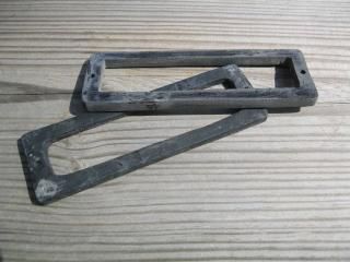
    FYI I made a very basic mold and poured a couple of 1/4" spacers (polyurethane casting resin) for the 747 ECM.


  4. #34
    Fuel Injected!
    Join Date
    Feb 2014
    Location
    Upstate, NY
    Posts
    416
    Is that to make the cover higher to clear the chips with certain adapters. If so pretty neat.

  5. #35
    Fuel Injected! EDZIP's Avatar
    Join Date
    May 2012
    Location
    Champlain, NY
    Age
    73
    Posts
    330
    Quote Originally Posted by joegreen View Post
    Is that to make the cover higher to clear the chips with certain adapters..
    Yes Sir...

  6. #36
    Fuel Injected!
    Join Date
    Feb 2014
    Location
    Upstate, NY
    Posts
    416
    I havent seen anything like that yet. Its a good solution and looks cheap to make. How did you make the mold?

  7. #37
    Fuel Injected! EDZIP's Avatar
    Join Date
    May 2012
    Location
    Champlain, NY
    Age
    73
    Posts
    330
    Quote Originally Posted by joegreen View Post
    I havent seen anything like that yet. Its a good solution and looks cheap to make. How did you make the mold?
    I have been making "rifle grips" for the AR www.RifleGrip.com and make my grip molds from silcone. When making the molds I have some left-over silicone, so I just carved a piece of wood into that shape and covered it with left-over silicone. Then when I have left-over resin..use it on the mold. Definitely not high tech..but I get to use leftover material "when I have extra".

    The resin is hard..but a flexible resin is available.

    Ed

  8. #38
    Fuel Injected!
    Join Date
    Feb 2014
    Location
    Upstate, NY
    Posts
    416
    Ok so my s2 zif and 27sf512 came in the mail today. The zif is of great quality. Anyway i took some pictures during the installation process so you can see how it turns out. When i tied the 5 pins together on the bottom of the zif i used maybe 4 or 5 strands of wire that i tinned then bent into the shape i wanted. I used a 30 watt soldering iron from harbor freight which works very well for the $7 i paid for it. I used the smallest tip i had for the soldering iron and some .032 rosin core solder from radio shack that i like alot. I did not have a solder wick or solder sucker to clean out the pin holes on the daughterboard so i used no9 lead from a mechanical lead pencil to poke through the holes when the solder was hot. When the solder cools you can pull the lead out and nothing sticks to it. If i had to do this again i would probably use the same method because i am cheap but i really recommend a solder sucker because i had to poke out all of the holes twice. Removing the stock chip holder was very easy. You just remove the plastic housing from the pins soldered to the board with a flat tip screwdriver very gently. you may have to break the glue seal between the plastic housing and the pcb. Then you can unsolder each pin individually. After the zif is all set and the pcb holes are opened then you can set the zif into the pcb and you are ready to solder from the bottom. One thing i had to do was bend the zif handle a little to clear the (mem cal) I think that is what it is called. You also have to cut this plastic pin that pops through the middle of the daughterboard because the zif covers the hole it came through. Once that is done you can do a continuity test on each of the pins next to each other to make sure that you did not solder some together. After that you can reassemble and are ready to pop in the 27sf512. Be warned this zif does not allow the cover to fit. You will probably need a low profile zif.
    Attached Images Attached Images
    Last edited by joegreen; 07-09-2014 at 01:06 AM.

  9. #39
    Carb and Points!
    Join Date
    Aug 2014
    Location
    Detroit Suburbs
    Posts
    9
    Followed Dave W's instructions in the first post. Turned out great. I had never looked at the chip pin outs closely before. Used a G2 w/ zif holder in the past for a different vehicle. Bought a low profile zif from Jameco through Amazon: http://amzn.com/B00B886OLW Pins are pretty fragile, but no issues once soldered in. Fits under the cover nicely.

  10. #40
    Fuel Injected!
    Join Date
    Feb 2015
    Location
    Ogden, UT
    Age
    40
    Posts
    139
    Will this mod also work on a 1228747 ECM?
    1990 Chevrolet K2500, RCLB, Blueprint 383 TBI (16197427 ECM / 61 lb/hr / 16 psi FP), NV4500, NP241C, 4.10

  11. #41
    Super Moderator dave w's Avatar
    Join Date
    Feb 2011
    Posts
    6,264
    Quote Originally Posted by Chewy1576 View Post
    Will this mod also work on a 1228747 ECM?
    Yes

    dave w

  12. #42
    Fuel Injected!
    Join Date
    May 2014
    Location
    Long Beach, CA
    Age
    64
    Posts
    23
    I had Dave do the conversion on 7747 I bought from him, this method is the way to go, no clearance issues with cover

  13. #43
    Fuel Injected!
    Join Date
    Jun 2016
    Location
    Charleston, SC
    Age
    52
    Posts
    162
    Dumb question- this is called a "Flash upgrade"- why is it called this if one must still burn and swap out the chip?

    In my field, "flash upgrade" means you can simply upload a new operating system or firmware for a system over a cable, no need to manipulate the hardware.
    -Phil, in Charleston, SC

    '89 S10 Blazer: SOA SAS: Dana 44s, 5.7L V8, 700R4; 35s, 4.10:1; TBI with 1227747 ECM
    '94 Grand Cherokee: 4.0, 4" lift, 31s
    '90 Jeep Cherokee: In progress: 5.7L V8,700R4,NP231C, D44s. TBI with 1227747 ECM
    '87 Fiero GT: 3.8SC (initial research stage)

  14. #44
    Super Moderator dave w's Avatar
    Join Date
    Feb 2011
    Posts
    6,264
    The 27SF512 chip is an Electronically Erasable Program Read Only Memory (EEPROM) chip. Most chip programmers can usually erase the 27SF512 chip in about second maybe even less time than that! EEPROM's can usually be fully programmed in a few seconds (3 to 5 seconds)

    The original 7747 chip is us ally a 2732a chip that is an Erasable Program Read Only Memory (EPROM) chip. EPROM's usually require exposure to Ultra-Violet light for about about 20 minutes to erase. The EPROM usually takes more about 2 minutes, sometimes more to be fully programmed

    So the "Flash" is basically how quickly the chip can be erased and reprogrammed. Basically, the 27SF512 can be erased and programmed in less time than it takes to remove the chip from a 7747 computer, even with the 7747 chip access cover removed.

    dave w

  15. #45
    Fuel Injected!
    Join Date
    Jun 2016
    Location
    Charleston, SC
    Age
    52
    Posts
    162
    OK thanks for the clarification. Is there a gm analog to the EBL setup?
    -Phil, in Charleston, SC

    '89 S10 Blazer: SOA SAS: Dana 44s, 5.7L V8, 700R4; 35s, 4.10:1; TBI with 1227747 ECM
    '94 Grand Cherokee: 4.0, 4" lift, 31s
    '90 Jeep Cherokee: In progress: 5.7L V8,700R4,NP231C, D44s. TBI with 1227747 ECM
    '87 Fiero GT: 3.8SC (initial research stage)

Similar Threads

  1. '427 PCM - Memcal Mod for 27SF512 Chip
    By dave w in forum Fuel Injection Writeups Articles and How to New and Old
    Replies: 13
    Last Post: 04-20-2012, 12:24 AM

Bookmarks

Posting Permissions

  • You may not post new threads
  • You may not post replies
  • You may not post attachments
  • You may not edit your posts
  •