

Thank you just a zif sounds great.


Thank you just a zif sounds great.

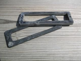
FYI I made a very basic mold and poured a couple of 1/4" spacers (polyurethane casting resin) for the 747 ECM.
Is that to make the cover higher to clear the chips with certain adapters. If so pretty neat.
Yes Sir...Originally Posted by joegreen

I havent seen anything like that yet. Its a good solution and looks cheap to make. How did you make the mold?
I have been making "rifle grips" for the AR www.RifleGrip.com and make my grip molds from silcone. When making the molds I have some left-over silicone, so I just carved a piece of wood into that shape and covered it with left-over silicone. Then when I have left-over resin..use it on the mold. Definitely not high tech..but I get to use leftover material "when I have extra".
The resin is hard..but a flexible resin is available.
Ed
Ok so my s2 zif and 27sf512 came in the mail today. The zif is of great quality. Anyway i took some pictures during the installation process so you can see how it turns out. When i tied the 5 pins together on the bottom of the zif i used maybe 4 or 5 strands of wire that i tinned then bent into the shape i wanted. I used a 30 watt soldering iron from harbor freight which works very well for the $7 i paid for it. I used the smallest tip i had for the soldering iron and some .032 rosin core solder from radio shack that i like alot. I did not have a solder wick or solder sucker to clean out the pin holes on the daughterboard so i used no9 lead from a mechanical lead pencil to poke through the holes when the solder was hot. When the solder cools you can pull the lead out and nothing sticks to it. If i had to do this again i would probably use the same method because i am cheap but i really recommend a solder sucker because i had to poke out all of the holes twice. Removing the stock chip holder was very easy. You just remove the plastic housing from the pins soldered to the board with a flat tip screwdriver very gently. you may have to break the glue seal between the plastic housing and the pcb. Then you can unsolder each pin individually. After the zif is all set and the pcb holes are opened then you can set the zif into the pcb and you are ready to solder from the bottom. One thing i had to do was bend the zif handle a little to clear the (mem cal) I think that is what it is called. You also have to cut this plastic pin that pops through the middle of the daughterboard because the zif covers the hole it came through. Once that is done you can do a continuity test on each of the pins next to each other to make sure that you did not solder some together. After that you can reassemble and are ready to pop in the 27sf512. Be warned this zif does not allow the cover to fit. You will probably need a low profile zif.
Last edited by joegreen; 07-09-2014 at 01:06 AM.
 Posting Permissions

 Reply With Quote
Bookmarks